A network can look healthy at 9:00 a.m. and still fail before lunch because one overlooked device, conduit, or maintenance step turns out to be the only thing holding the service together. A single power supply trips. One upstream fiber route gets cut by road work. A software upgrade on the “standby” unit reveals that it hasn't been able to take traffic for weeks. Operators then discover the hard truth: they didn't have resilience. They had assumptions.
That's why redundancy engineering matters. In telecom and data-center work, uptime isn't a lucky outcome. Teams have to design it into power, transport, routing, cooling, and facility operations. They also have to prove that the design still works when technicians touch it, patch it, or replace parts under pressure.
Learn the labels first: N, N+1, 2N. Those labels help, but they don't answer the two questions that cause the most field trouble. Are the “redundant” paths independent? And what happens to redundancy during maintenance? Those are the gaps where paper designs fail in live operations.
Introduction Why Networks Fail Without Redundancy
A site can pass its morning checks and still suffer a service outage by noon. Utility power drops at a remote cabinet. The battery string carries the load for a moment, but one weak connection or undersized backup path keeps it from holding steady. Traffic shifts, alarms pile up, and a fault that started in one cabinet spreads into transport, backhaul, and user sessions.

That pattern matters because network failures rarely stay contained. One failed optic can push traffic onto a path that was already near capacity. One cooling problem can force equipment to slow down or shut off to protect itself. One shared upstream handoff can isolate a building full of healthy gear. The first fault is often survivable. The outage grows when the design gives that fault only one way to spread.
In postmortems, the failed part is often the trigger, not the full cause. The weakness is usually older than the alarm. Both fiber routes entered through the same duct bank. The A and B feeds traced back to the same panelboard. The standby router existed on paper, but no one had proven it could carry production traffic.
This is why labels such as N+1 and 2N only tell part of the story.
Two generators in one flood zone are still one failure domain. Two routers that depend on the same software image, patch process, and upstream switch can still fail together. A design can look redundant on a rack diagram and still collapse during a maintenance window because taking one component out of service removes all real protection.
That is the gap operators need to see clearly. Redundancy is not just extra equipment. It is independence between paths, power sources, control planes, and physical routes. It is also the ability to service one side without betting the whole site on the other side behaving perfectly.
A good way to picture it is a hospital with two entrances that both use the same bridge. On paper, there are two ways in. In practice, the bridge is the site. Networks and data centers fail for the same reason. The duplicate components get attention, while the shared dependency does not.
The design questions are practical ones:
- Do the primary and backup paths fail for different reasons, or the same reason?
- What protection is left when a technician shuts one side down for maintenance?
- Which shared dependencies could turn a single fault into a site outage?
Operators, facility teams, and IT staff make these choices every day. They decide whether a hub needs diverse entrances, whether cabinet rows need true A and B power distribution, and whether a standby unit has been tested under live conditions or only assumed to be ready. Those decisions determine whether redundancy exists in the field or only in the drawing set.
What Redundancy Engineering Really Means
At the simplest level, redundancy engineering means building a system so it can keep working when a part fails. The easiest analogy is a spare tire. If one tire fails and you can still continue the trip, you had a workable backup. But networks and data centers are closer to a city road system than a car. The better analogy is having more than one route to the same destination, and making sure those routes don't all merge at the same collapsed bridge.
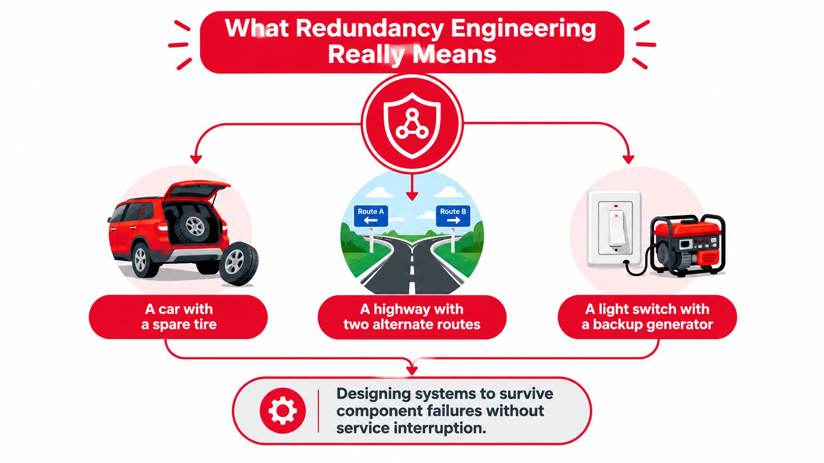
Redundancy is not the same as backup
People often mix up backup, high availability, and fault tolerance. They're related, but they're not the same thing.
A backup is something you restore later. A fault-tolerant system keeps running through the failure itself. High availability sits between those ideas. It aims to keep interruption brief and controlled, even if the service has to switch over.
Key concept: A backup helps you recover after an interruption. Redundancy helps you avoid the interruption in the first place.
That distinction matters in operations. A config backup won't help if a single failed power shelf takes down both routers now. A spare module in storage won't help if your service target requires continuity while the failed module is being replaced.
Single points of failure are the real enemy
A single point of failure is any component, path, or dependency whose loss stops the service. That point can be obvious, like one core switch, or hidden, like two circuits ordered from different providers that still share the same duct bank for part of the route.
In practical terms, redundancy engineering asks four plain questions:
- What can fail? Hardware, fiber, software, utility power, cooling, human process.
- What happens next? Degraded service, hard outage, latency spike, loss of management access.
- What survives automatically? The spare chassis, alternate route, second feed, or standby generator.
- What still depends on the same thing? Shared conduits, common breakers, common control planes, or common maintenance procedures.
It spans more than one technical layer
A lot of teams think about redundancy at only one layer. Network teams focus on routers and transport. Facilities teams focus on UPS and generators. Server teams focus on clustered compute. Outages don't respect those boundaries.
A resilient environment usually needs redundancy across multiple layers at once:
- Power layer: Dual feeds, UPS, generator support, separate distribution paths
- Connectivity layer: Diverse carriers, diverse entrances, alternate transport paths
- Cooling layer: Spare capacity so one cooling component can fail without overheating the load
- Compute and control layer: Clustered services, redundant controllers, failover logic
If one of those layers remains singular, the whole service can still be singular.
Types of Redundancy in Network and Data Center Infrastructure
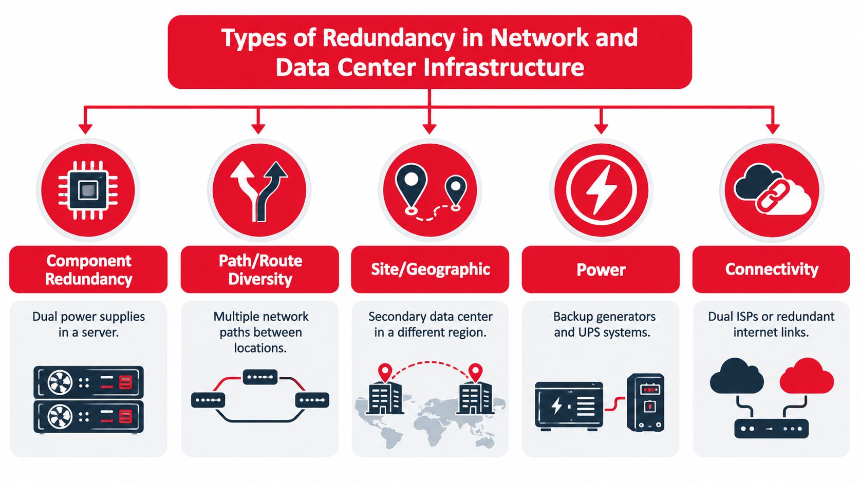
The quickest way to clear up confusion is to map each kind of redundancy to the failure it is supposed to prevent. Teams waste time when they solve the wrong problem well. Dual power supplies won't save you from a fiber cut. A second carrier won't help if both circuits enter through the same handhole.
Component redundancy
This is the most familiar type. You duplicate a device or module so a single hardware failure doesn't stop the service. Think dual power supplies in a server, a spare line card, or a router pair where one unit can carry the load if the other fails.
Component redundancy protects against part failure inside a system. It does not, by itself, protect against a shared rack PDU, a software bug present on both units, or a fiber path that reaches only one device.
Path and route diversity
Telecom teams spend a lot of time on path diversity, and for good reason. It gives traffic another physical route if one path is cut or blocked. In fiber networks, that can mean separate laterals, separate conduits, or transport rings that don't collapse around a single street crossing.
The tricky part is proving the paths are separate. Teams responsible for telecommunications infrastructure asset management often emphasize route records, plant visibility, and field documentation because route diversity on paper can disappear in the outside plant if records are incomplete or vendor paths converge without notice.
Site and geographic redundancy
Some risks are bigger than a device or a cable. Flooding, utility failure, fire, and regional events can affect an entire building or market area. Site redundancy places the service in more than one facility. Geographic redundancy spreads critical functions farther apart so one local event doesn't disable all service capacity.
This is common for core workloads, mobile switching functions, and services that need continuity even when a building becomes unavailable.
Power redundancy and connectivity redundancy
Power redundancy covers the electrical chain from utility service through UPS, generators, switchgear, PDUs, and rack delivery. Connectivity redundancy focuses on the logical and commercial side of network access: multiple upstreams, cross-connect diversity, and alternate interconnection points.
These are often discussed separately, but in live operations they interact. A meet-me room can be perfectly diverse from a carrier perspective and still fail if both carrier shelves depend on the same power distribution point.
| Redundancy Type | Failure It Prevents | Typical Application |
|---|---|---|
| Component Redundancy | Single hardware or module failure | Dual power supplies in a server, paired routers |
| Path and Route Diversity | Fiber cut or blocked transport route | Diverse conduit paths, ring transport, dual building entrances |
| Site and Geographic Redundancy | Whole building or regional disruption | Secondary data center, alternate core site |
| Power Redundancy | Utility loss or electrical component failure | Dual UPS paths, generator-backed distribution |
| Connectivity Redundancy | Upstream carrier or interconnect loss | Multiple carriers, diverse cross-connects |
Many outages blamed on “equipment failure” are actually design failures. The equipment failed once. The design failed to contain it.
Design Patterns and How Availability Is Calculated
A midnight UPS maintenance window is where a lot of “redundant” designs get their first honest test. On paper, the site may be N+1 or even 2N. In the room, one breaker is open, one path is carrying more than expected, and a shared control panel or switchboard suddenly matters more than the label on the diagram.
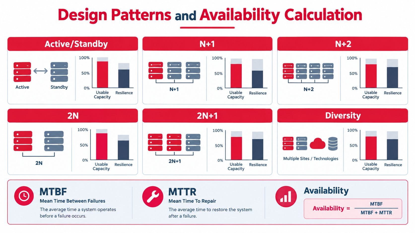
That is why design patterns need to be read in two layers. The first layer is capacity. How much spare equipment do you have? The second is independence. Can one side fail, or be taken out of service for planned work, without dragging the other side down with it?
What the main patterns mean in practice
Active standby uses one production system and one waiting system. It works well for router pairs, firewalls, controllers, and clustered services when failover is fast and the standby is ready to carry the full live load. A standby node that has stale state, reduced licensing, or untested failover timing is only partial protection.
N means the installed equipment exactly matches the required load. If any required unit fails, the service has no cushion.
N+1 adds one spare unit above the required number. If a single module, UPS, chiller, or service node fails, the extra unit should absorb the loss.
N+2 adds two spare units. Teams use it where one spare is not enough for the fault model or where maintenance often overlaps with a possible in-service failure.
2N provides two full-capacity paths. Either side can support the load by itself, assuming the paths are independent.
2N+1 starts with two complete paths and adds extra spare capacity on top. That extra margin is often aimed at high-consequence environments where teams want room for both failure and maintenance.
Diversity sits beside all of those patterns. It is about separation, not quantity. Two UPS systems in the same flood zone, on the same switchboard, with the same controls, are duplicated equipment inside one failure domain.
That last point is where paper redundancy often breaks. A site can have plenty of spare capacity and still have weak resilience because both “independent” paths cross the same room, rely on the same automation, or require the same technician action during an event.
Capacity labels are only the starting point
Count-based patterns are useful because they show how much of the installed plant is reserved for failures or maintenance. In practical terms, higher redundancy usually means less of the total installed capacity is treated as normal working capacity. That tradeoff is why finance teams, facilities teams, and network teams often look at the same design and see different priorities.
The label also says very little about maintenance-window fragility. An N+1 design may survive a single failure during normal operation, then become exposed the moment one unit is isolated for service. A 2N design usually gives more room for concurrent maintenance, but only if each side has real electrical, mechanical, and control-path independence.
A simple way to read the architectures
| Architecture | What it really gives you | Where it can still fail |
|---|---|---|
| N | Required capacity only | Any required component outage can affect service |
| N+1 | One spare unit | A second fault, a shared upstream dependency, or maintenance on the wrong common point |
| N+2 or 3N/2 | More spare coverage than N+1 | Shared controls, shared distribution, or incorrect load assumptions |
| 2N | Two full-capacity paths | Cross-ties, common switchgear, common fuel, common software, or human error affecting both sides |
| 2N+1 | Dual full-capacity paths plus extra spare margin | The same independence risks as 2N, plus unnecessary complexity if operations are weak |
The table is a design shorthand, not a promise. Operators should always ask two follow-up questions. What is the largest single failure domain in the design? What happens when one side is already out for maintenance?
How availability is actually discussed
Availability math sounds abstract until you tie it to operations.
- MTBF means mean time between failures. It is the typical operating time before a component fails.
- MTTR means mean time to repair. It is the time needed to restore the failed item or affected service.
- Availability is commonly expressed as MTBF divided by MTBF plus MTTR.
Those terms matter because redundancy affects service impact, while maintainability affects recovery speed. A design with spare capacity can contain a failure. A design with clear isolation points, stocked spares, and good access can shorten repair time. You need both.
For facility-level resilience, operators often refer to the Uptime tier model. One summary maps Tier I to 99.671% uptime, Tier II to 99.741%, Tier III to 99.982%, and Tier IV to 99.995%, which is about 28.8 hours, 22.7 hours, 1.6 hours, and roughly 26 minutes of annual downtime, according to Backup Power on N+1 vs 2N generator redundancy.
A separate technical overview connects those higher availability targets to topology and maintainability. It explains that moving from single-path N designs to N+1, 2N, and 2N+1 architectures removes single points of failure and supports concurrent maintenance, as outlined by Socomec on data center redundancy and reliability.
The practical lesson is simple. Availability does not come from buying more gear alone. It comes from containing failures inside small domains and keeping routine maintenance from turning a healthy design into a temporary single-threaded system.
Testing Validation Monitoring and Maintenance Practices
At 2:00 a.m., a technician opens a breaker for planned maintenance on feed A. The room stays up, so the design looks healthy. Ten minutes later, a stuck transfer switch alarms on feed B, and now a site that looked redundant on paper is running out of good options. That is how many real outages begin. The first event is planned. The second event exposes the hidden coupling.
Testing has to answer two practical questions. Are the failure domains independent, and what happens when maintenance removes one layer of protection? Labels like N+1 and 2N do not answer either one by themselves.
Prove independence before you prove failover
A and B paths should work like two separate roads to the same destination. If both roads cross the same bridge, the map shows diversity but the bridge still controls both routes. The same mistake shows up in power, cooling, transport, and management networks.
Guidance on data-center reliability makes this point clearly. Shared power, cooling, or network elements can turn spare capacity into a single failure domain, as discussed by Data Center Guidelines on data center reliability.
Start by checking what the drawing can hide:
- Physical separation: A and B feeds, fibers, and devices do not pass through the same room, tray, riser, duct, or handhole where one event can hit both.
- Control separation: Two active paths do not depend on one controller, one software image, one management switch, or one shared automation action to stay safe.
- Support-system separation: The “independent” network path is not tied to the same UPS branch, cooling zone, GPS source, or timing server.
- Documentation and labeling: As-built drawings, panel labels, circuit IDs, and patch records match the plant technicians will touch.
This step sounds basic. It is also where paper redundancy often fails.
Test the design in the condition it spends time in
Operators rarely live in the neat, fully protected state shown in a design review. They live in the maintenance state. One card is out for replacement. One UPS is in bypass. One route is suppressed after a flap. One software train is halfway through upgrade approval.
Recent coverage on modular and N-version redundancy points to the same operational problem. Protection can shrink during upgrades and planned work, so testing has to include fault conditions and reduced-protection conditions, as noted in this ArXiv survey on N-version and modular redundancy.
That changes the test plan. A single pull test is not enough. You need to know whether the surviving path can carry load, alarm correctly, and stay stable while one layer is already unavailable.
A practical validation cycle usually looks like this:
- Define the expected behavior. Write down what should happen if a feed fails, a router reloads, or a transport leg drops.
- Run a controlled event. Trigger the failover and watch service impact, timing, alarms, and operator visibility.
- Repeat in a maintenance state. Put one redundant element in bypass, isolated, or out of service, then repeat the event.
- Compare reality to the procedure. Fix the diagram, runbook, thresholds, or hardware assignment when the field result differs from the plan.
Monitor for survivability, not just status
A green dashboard can still hide a weak system. A pair of devices may both be up while one side is overloaded, one battery string is weak, or failover has been disabled since the last change window.
The better question is simple: if one side fails right now, will the other side hold long enough for operators to respond?
That means watching conditions such as:
- Current role and protection state: active, standby, bypass, degraded, inhibited, on battery, generator available
- Remaining capacity: whether the surviving path can carry the present load without crossing safe limits
- Path quality: interface errors, optical power drift, CRCs, latency changes, flap history, and environmental alarms
- Recent changes: firmware loads, config edits, maintenance tickets, disabled interlocks, and test overrides left in place
Outside-in visibility helps here too. Internal alarms may say every component is up while users still see a broken service path. A simple example is how MetricsWatch tracks uptime, which is useful when you want to compare customer experience with what the infrastructure alarms report.
Maintenance discipline is part of the redundancy design
A redundant system can become single-threaded because of a rushed procedure, not a hardware shortage. Good maintenance practice treats every planned action as a temporary redesign of the site.
Use pre-work checks that answer three things before hands touch gear: what protection is already missing, what hidden dependency could make this task wider than expected, and what stop condition tells the technician to pause. Then use post-work checks to confirm the system returned to its intended protected state, not just that the immediate task was completed.
That is the difference between owning spare equipment and operating a resilient facility.
Cost Versus Risk and Real World Implementation Examples
A site can look fully protected on paper and still be one maintenance ticket away from an outage.
That is the cost discussion many teams miss. The decision is not only how many extra components to buy. It is how much independence to build between failure domains, and how much fragility to accept when one path is out for service. A design that survives a single fault in a diagram may still fail during routine work if both paths share the same entrance, controls, crew procedure, or overloaded survivor path.
Why lower efficiency can still be the cheaper choice
As noted earlier, higher resilience reduces usable capacity. That can feel wasteful until you compare it with the cost of an interruption, the recovery effort, and the customer impact that follows.
A simple way to frame it is to compare a fire truck with spare seats versus one filled to every inch. Full utilization looks efficient right up to the moment something goes wrong. Redundancy reserves room for failure, for maintenance, and for the surprises that never appear in a tidy rack diagram.
This is why some teams accept a design that carries less normal load per installed unit. They are buying options under stress. They are also buying safer maintenance windows, because the site can keep operating while one side is isolated, tested, or repaired.
Three practical implementation examples
A fiber broadband aggregation site often gets more value from route independence than from duplicating electronics first. If both "redundant" fibers enter through the same duct bank or terminate in the same handhole, one civil cut can remove both. Separate laterals, separate entrances, and accurate splice records may reduce risk more than adding another chassis in the same room.
A data-center fit-out for critical compute usually exposes a different weak point. The headline question is not only whether A and B power paths exist. It is whether they stay independent during maintenance. If both paths depend on the same control panel, the same upstream breaker lineup, or a change procedure that temporarily lands both feeds in the same state, the site can become single-threaded exactly when staff believe it is protected.
A wireless deployment often benefits from selective redundancy. Full duplication of every subsystem may not be justified, but some elements fail "loudly" across many services. Backhaul handoff, timing, and the power chain usually deserve stronger separation than less critical support equipment. The right answer is not blanket 2N. It is protecting the parts that create the widest service loss if they fail together.
A simple decision matrix
Use this reasoning when choosing between N+1 and 2N:
- Choose N+1 when the service can tolerate reduced protection during some maintenance activities, budget pressure is real, and a spare unit lowers the most likely equipment failure risk.
- Choose 2N when the service must stay up through both faults and planned work, and each path can remain physically and operationally independent all the way upstream.
- Reconsider both when the design still hides a shared failure domain such as a common entrance, common fuel dependency, common controls, common cooling exposure, or a procedure that places both sides at risk during the same work window.
One practical implementation choice is to use a contractor that handles both build and lifecycle support. In telecom and data-center projects, Southern Tier Resources provides engineering, construction, testing, documentation, and ongoing maintenance, which can help teams keep the installed redundancy understandable and supportable after turnover.
Putting Redundancy Engineering Into Practice
A site can look fully protected on paper and still fail during a routine maintenance window.
That usually happens for two reasons. The first is hidden dependence between paths that were labeled as separate. The second is a backup path that only works until one side is out of service for planned work. Operators see this in the field all the time. A rack has dual feeds, but both controls report through one switch. A network has diverse fiber, but both routes enter through the same handhole. A generator plant has spare capacity, but one fuel arrangement supports both sides.
The practical goal is simple: build a system that can lose one element, survive planned work, and still keep carrying the service. Redundancy works like having two roads out of town only if those roads do not merge at the same bridge.
A useful field checklist starts with service impact, then follows each dependency until the weak points show up.
- Rank services by consequence: Separate loads that must stay up from loads that can tolerate restoration after an interruption.
- Trace each failure domain end to end: Follow power, fiber, cooling, timing, management, and control paths until you find every shared segment.
- Choose the pattern for the exposure: Use N, N+1, or 2N based on what must survive faults and what must stay protected during maintenance.
- Test degraded states on purpose: Verify failover during normal operation, then repeat the test with one path unavailable for maintenance.
- Keep operating records current: Update labels, route diagrams, as-builts, inventories, and runbooks after every material change.
- Monitor carrying ability, not just alarm status: Confirm the surviving path has the headroom and correct configuration to carry the full load.
- Treat standby equipment like active equipment: Patch, exercise, inspect, and capacity-check the backup path so it does not decay.
The maintenance test is where many designs are exposed. A dual-corded load may survive a power supply failure but still drop if one upstream panel is isolated for service and the remaining path was never sized, configured, or documented for full demand. The same pattern shows up in network routing. A secondary path exists, but the QoS policy, optics inventory, or cross-connect documentation lags behind production reality.
Good redundancy engineering is careful work shared across operations, network, facilities, and project teams. Hardware counts matter, but real continuity comes from independent failure domains, clean documentation, and repeated proof under maintenance conditions.
Southern Tier Resources supports carriers, ISPs, wireless operators, and data-center teams with engineering, construction, testing, documentation, and maintenance for redundant network and facility infrastructure. If you're evaluating route diversity, power-path independence, or maintenance-ready infrastructure, visit Southern Tier Resources to see how they support resilient deployments end to end.