

In the telecom and data center world, we talk a lot about uptime, resilience, and five-nines reliability. But what actually makes all that possible? It comes down to a collection of unsung heroes: the Bell power systems that work tirelessly behind the scenes.
These aren't just glorified backup batteries. They are complete, highly redundant DC power plants that serve as the bedrock of our digital lives, providing clean, uninterrupted power to everything from massive data centers to remote cell towers.
The Unseen Engine Powering Modern Networks

Think of a Bell power system as the heart of the network. It’s the life-support system that ensures your calls go through, your data gets where it needs to be, and the cloud services you depend on never falter. The name itself is a nod to the old Bell System, which established the original gold standard for reliability that we still strive for today.
At its core, a Bell system’s job is twofold. First, it takes the standard AC power from the utility grid and converts it into the stable -48V DC power that most modern telecom and network gear is designed to run on.
More importantly, it acts as a fortress against power failure. Whether it's a momentary voltage sag or a multi-day blackout, the system is designed to provide a seamless transition to backup power, keeping the network online without a single hiccup.
Why Downtime Is Not an Option
In our always-connected world, an outage is more than an inconvenience; it’s a catastrophe. A few hours of downtime can translate into millions of dollars in lost revenue, a flood of angry customers, and a bruised reputation that takes years to repair.
This is why experienced operators don't see robust power infrastructure as just another line item on a budget. It’s a foundational business continuity strategy. A well-designed Bell power system is your primary defense against these failures.
The true value of a Bell power system is measured not in its cost, but in the revenue and reputation it protects. It transforms power from a potential point of failure into a source of guaranteed operational resilience.
This guide is designed to cut through the dense technical specifications and give you a practical understanding of how these critical systems work. We'll break down the key components, explore common design philosophies, and walk through the maintenance routines that keep everything running smoothly.
Our goal is to demystify these systems and show you how they create a truly dependable digital future. We’ll cover essential topics for anyone involved in designing, managing, or investing in critical infrastructure:
- Core Components: From rectifiers and batteries to generators and transfer switches.
- Design & Redundancy: A look at N+1, 2N, and other common architectures.
- Real-World Use Cases: Practical applications in cell sites, central offices, and data centers.
- Maintenance Best Practices: How to ensure long-term reliability and stay compliant.
Understanding the Core Components
To really get a feel for how Bell power systems achieve such incredible reliability, we need to look under the hood. The best way to think about it is like the electrical system in a vehicle, where every single part has a specific, critical job. When they work together, they form layers of defense that ensure your equipment never goes dark.
This isn’t just a simple backup battery. It’s a carefully engineered sequence of events, designed from the ground up for an immediate and sustained response to any power problem. Let's pull back the curtain on each component to see how they form a single, resilient system.
The Rectifier: Powering the Present
First up is the AC-to-DC rectifier. This is the unsung hero of any Bell power system, working silently around the clock. Think of it as your facility’s personal currency exchanger. It takes the alternating current (AC) coming from the utility grid—the "foreign currency"—and converts it into the direct current (DC) that your equipment actually uses.
Specifically, it transforms the grid’s standard 208V or 480V AC power into the clean, stable -48V DC that is the native language of virtually all modern telecom and data center hardware. This steady DC voltage is absolutely essential for the sensitive electronics packed inside your routers, switches, and servers.
But the rectifier has another equally important job. It also keeps the system’s first line of defense—the batteries—ready for action. It supplies a constant "float charge" to the battery plant, keeping them perfectly topped off without overcharging, which is key to preserving their health and lifespan.
The Battery Plant: Bridging the Gap
The second the AC power from the utility fails, even for a fraction of a second, the battery plant takes over instantly. This is the system's massive-scale uninterruptible power supply (UPS). There's no delay, no switching time, and absolutely no interruption to the DC load.
These batteries are the crucial bridge covering the gap between the moment utility power is lost and the moment a backup generator can fire up and get stable. That "ride-through" time is everything. Even a momentary blip in power can force network gear to reboot, dropping calls and killing data sessions in the process.
Let's take a look at the core components of these systems and their roles.
Core Components and Their Functions
This table offers a quick snapshot of the primary parts of a Bell power system, what they do, and how they contribute to overall reliability.
| Component | Primary Function | Role in Power Redundancy |
|---|---|---|
| Rectifier | Converts utility AC power to -48V DC power. | Powers the DC load and continuously charges the backup batteries. |
| Battery Plant | Provides instantaneous DC power during an AC failure. | Acts as the immediate, no-break bridge between grid failure and generator startup. |
| ATS & Generator | Monitors utility power and starts the generator when it fails. | Supplies long-term AC power to the rectifiers during an extended outage. |
Each of these elements works in a coordinated sequence, handing off the responsibility of powering the site seamlessly.
There are two main battery chemistries you’ll find in the field:
- Valve-Regulated Lead-Acid (VRLA): For years, VRLA has been the go-to standard. It’s a reliable, cost-effective solution with a proven track record you can trust.
- Lithium-ion (Li-ion): As the more modern option, Li-ion batteries pack more power into a much smaller and lighter package. They also last longer and handle more charge cycles, though their upfront cost is higher.
The size of the battery plant is always engineered specifically for the site, calculated to provide enough runtime—anywhere from minutes to hours—to keep things online until long-term power is secured.
The Automatic Transfer Switch and Generator
While batteries provide that essential, instant buffer, they can’t run forever. For outages that stretch beyond a few minutes, you need a more sustainable power source. This is where the Automatic Transfer Switch (ATS) and the backup generator step in.
The ATS is the smart decision-maker in this setup. Its only job is to watch the incoming utility feed. The instant it detects a power failure or instability, it signals the generator to start.
Once the generator is running and putting out stable AC power, the ATS flawlessly transfers the facility’s entire electrical load—including the rectifiers—from the dead utility line over to the live generator feed.
This orchestrated handoff is the very foundation of long-term power resilience. The batteries handle the immediate, sub-second transition, while the ATS and generator provide indefinite power for hours or even days, ensuring total business continuity through a prolonged blackout.
After the utility restores stable power, the ATS waits for a pre-set amount of time to ensure it's reliable, then intelligently transfers the load back and shuts the generator down. For a deeper dive into how power moves through these facilities, check out our guide on data center power distribution systems. This entire sequence happens automatically, without a single person needing to flip a switch, creating a truly robust defense against any power disruption.
Real-World Applications in Telecom and Data Centers
So, we've covered the theory. But where do Bell power systems really prove their worth out in the field? At their core, these systems are purpose-built to deliver clean, uninterrupted power exactly where it matters most. They are the unsung heroes keeping our connected world online, from the most remote cell sites to sprawling cloud data centers.
In the telecom world, these systems are simply non-negotiable. They are the heartbeat of central offices, fiber optic hubs, and the countless remote facilities that make up our communication backbone. Every switch, router, and optical terminal runs on the stable -48V DC power these systems provide. Take that away, and the service goes dark.
This obsession with reliability has deep roots. The original Bell System—affectionately known as Ma Bell—set the gold standard for uptime during its century-long dominance of North American telecom, which began in 1877. When the company was broken up in 1984, its culture of near-perfect reliability had already become the benchmark for the entire industry. That event also kicked off a wave of innovation, paving the way for the advanced fiber and wireless networks that companies like Southern Tier Resources build today. You can learn more about this fascinating history of the Bell System and its lasting impact.
Powering a Rural 5G Small Cell Deployment
Let's look at a classic example: deploying 5G in a rural area. A small cell needs to be mounted on a utility pole or the side of a building to serve local customers. The problem is, the local power grid can be spotty, and getting a technician to the site isn't always easy. This scenario is a perfect fit for a compact Bell power system.
- The Challenge: An unreliable grid leads to frequent service drops, frustrating customers and hurting the return on the 5G investment.
- The Solution: A small-footprint power cabinet is installed right at the site. Inside, a rectifier converts AC grid power to DC, while a small battery bank stands ready for instant backup. The system also includes a connection for a portable generator.
- The Result: When a short power outage hits, the batteries take over so seamlessly that no one's call or data session is dropped. For a longer outage, a technician can simply hook up a generator, letting the site run for as long as needed. The outcome is city-grade reliability in a rural environment.
This diagram shows how these different pieces fit together to create a layered defense against power failure.
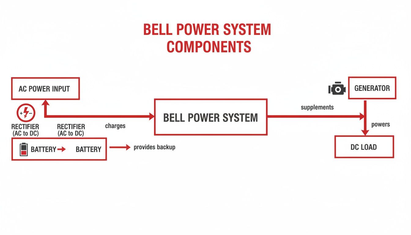
As you can see, the system creates a clear path from the primary AC source to the critical equipment, with both batteries and a generator ready to step in at a moment's notice.
Ensuring Uptime for a Cloud Availability Zone
When you move into the data center world, the stakes get exponentially higher. For a major cloud provider, even a minute of downtime can affect thousands of businesses and trigger millions in losses. Here, Bell DC power systems are fundamental to the A/B power feed architecture—the gold standard for fault tolerance.
In a hyperscale data center, the power system isn’t just another piece of equipment; it is the foundation of the entire service. Redundancy isn't a feature—it is the product.
This design is all about creating two completely independent power paths, labeled "A" and "B," that feed every single server rack. Each path has its own dedicated rectifiers, battery strings, and distribution panels. Servers and network gear with dual power supplies are then plugged into both paths at the same time.
If the "A" feed ever fails—whether from a bad rectifier or just a tripped breaker—the equipment doesn't even blink. It continues pulling power from the "B" feed with absolutely zero interruption. It's this level of redundancy, built on rock-solid DC power systems, that allows cloud providers to guarantee their aggressive Service Level Agreements (SLAs) and protect against catastrophic failures.
Designing for Reliability and Scalability
You can have the best components money can buy, but without a smart design, your power system is just an expensive liability. The most advanced rectifiers and batteries in the world won’t save you from an outage if the system wasn't architected with foresight. This is where the real work happens—balancing immediate costs against long-term operational risks to build a power infrastructure that is truly bulletproof.
At the core of any resilient design is one guiding principle: redundancy. The entire goal is to methodically eliminate every single point of failure. Think of it like building a series of safety nets. If one component fails, there's always another ready to catch the load, ensuring the system continues running without a single hiccup.
This obsession with reliability isn't new; it’s baked into the DNA of telecom. It traces its roots back to the original Bell System's research powerhouse, Bell Labs. Formally established in 1925, their work—including the 1947 invention of the transistor—set the standard for modern electronics. That legacy of focusing on fundamental reliability continues to shape how we build critical infrastructure today.
Understanding Redundancy Models
To achieve redundancy, we strategically deploy extra components that can take over in an emergency. The approach you take—whether it's N, N+1, or 2N—is one of the most important decisions you'll make, directly impacting your system's resilience, complexity, and budget.
So, let's break down what these models actually mean in practice.
A comparison of these common redundancy models shows the trade-offs between cost and protection.
| Redundancy Model | Description | Typical Use Case | Cost Level | Uptime Protection |
|---|---|---|---|---|
| N | The minimum number of components needed to power the load. No spares. | Non-critical sites, test environments where downtime is acceptable. | Low | None. A single component failure causes an outage. |
| N+1 | The minimum components needed (N) plus one additional spare component. | Most telecom sites, enterprise data centers, colocation facilities. | Moderate | Good. Protects against the failure of a single component. |
| 2N | Two fully independent and mirrored power systems (A and B side). | Mission-critical financial data centers, major network hubs, cloud providers. | High | Maximum. Can sustain an entire system failure without impact. |
As you can see, choosing the right model isn't just a technical exercise; it's a business decision based on your site's specific uptime requirements and tolerance for risk.
The decision between N+1 and 2N is a strategic trade-off. N+1 offers excellent protection for a moderate cost, while 2N provides the ultimate fault tolerance for applications where even a moment of downtime is unacceptable.
Sizing Your System for Today and Tomorrow
Once you've settled on a redundancy model, the next step is to calculate the precise capacity your system requires. This isn't guesswork; it's a careful science that balances your current needs with your future ambitions. This involves two critical calculations.
First is the load calculation. This means adding up the power consumption of every single piece of equipment the system will support, which gives you the "N" value for your redundancy model. A common mistake here is to plan only for what you have running today. A truly robust design always plans for at least 15-20% future growth, giving you the headroom to scale without a costly system overhaul down the road.
Second is battery sizing. This calculation determines how long your site can operate on battery power alone before the generator needs to kick in. This "runtime" is a crucial business decision. A remote cell site might only need 4 hours of battery backup, whereas a critical data center might demand 8 hours or more. For complex facilities, a custom electrical design is often the only way to ensure these specific requirements are met perfectly.
These design principles are the foundation of any resilient facility. To see how these power systems fit into the bigger picture, you can explore our overview of data center infrastructure solutions. Ultimately, physical site planning—accounting for the floor loading of heavy battery strings, ensuring proper ventilation for heat-producing rectifiers, and integrating with site-wide monitoring—ties all these elements together, turning a collection of parts into a cohesive, reliable power plant.
Maintenance and Testing Best Practices
Putting a new Bell power system on the floor is a great first step, but it doesn't guarantee uptime. The real work—the part that ensures your site stays online through anything—starts the day after commissioning. This is where a disciplined, proactive maintenance program comes in.
Think of it this way: you wouldn't buy a world-class race car and then skip the oil changes and tune-ups. Over time, even the best-built systems drift. Battery capacity fades, rectifier settings wander, and connections work themselves loose. Without consistent care, you're not managing a reliable asset; you're just waiting for a failure.
This obsession with uptime is baked into the DNA of telecom. It goes back to the original Bell System's culture, driven by work at Bell Labs that produced breakthroughs like the feedback amplifier in 1927. After the historic 1984 breakup, innovation exploded, with U.S. telecom patenting jumping 19.0% annually. That surge in R&D gave us the advanced infrastructure these power systems are now built to protect. You can find more detail on this pivotal industry shift and its effect on R&D in this in-depth analysis of the Bell breakup.
Establishing a Routine Maintenance Cadence
A solid maintenance program runs on a predictable schedule. It’s a living document that clearly defines what gets checked, how often, and why it matters. This isn't just about ticking boxes; it's about building a long-term health record for your entire power infrastructure. Many of these principles overlap with best practices for large-scale power plant operation and maintenance.
Your schedule should blend frequent, quick check-ins with less frequent, deep-dive diagnostics.
Monthly Checks: These are simple visual sweeps for your on-site team. Look for alarms on the plant controller, check for any corrosion on battery posts, confirm all rectifiers show green, and make sure vents are clear and fans are spinning.
Quarterly Maintenance: Here, a technician needs to start taking notes. They should be logging key readings like float voltage, individual rectifier currents, and the room’s ambient temperature. This data is what helps you spot a problem developing over months.
Annual and Bi-Annual Testing: This is the comprehensive physical. It involves in-depth battery capacity tests, full rectifier calibration, and functional testing of automatic transfer switches under simulated outage conditions.
Critical Testing Procedures
Visual checks are important, but you need hard data to truly prove your system is ready. These procedures are non-negotiable for verifying readiness and meeting standards from bodies like the IEEE and NFPA.
A maintenance log is not just a record of work done; it's a predictive tool. By tracking performance data over time, you can spot the subtle signs of component degradation and replace parts based on data, not guesswork.
1. Battery Impedance Testing
If you only do one deep test, make it this one. Impedance testing is the best crystal ball we have for predicting battery failure. By measuring the internal resistance of each battery in a string, you can spot a weak link long before it fails to carry the load. A steadily rising impedance value is a clear signal that a battery is on its way out.
2. Generator Load Bank Testing
Just starting the generator once a month proves very little. You have to prove it can handle the site’s full electrical demand for an extended time. A load bank test does exactly that by applying an artificial electrical load, forcing the generator to run at or near its full rated capacity for hours. It’s the only way to truly validate that the engine, cooling system, and fuel delivery are ready for a real-world blackout.
3. Rectifier Calibration and Functional Checks
Your rectifiers need to work as a team. A technician must verify they are sharing the load equally and that their output voltage is dialed in perfectly. If one rectifier is carrying more of the load, it will fail prematurely. Likewise, if the voltage is too high or too low, you risk damaging your expensive battery plant and the critical equipment it protects.
Your Project Procurement and Implementation Checklist
A great design on paper is one thing, but bringing a Bell power system to life—on time and on budget—is where projects truly succeed or fail. Moving from blueprint to a fully operational system demands a clear, disciplined approach.
Think of this checklist as your roadmap. It breaks down the entire process into manageable phases, helping you avoid the common pitfalls that can derail even the most well-intentioned projects. We’ll walk through everything from initial planning to the final handshake.
Phase 1: Laying the Groundwork
Before a single piece of equipment is ordered, you have to nail the fundamentals. This first phase is all about defining the "what" and the "who." Getting these details right from the start is non-negotiable, as every decision made here will echo through the rest of the project.
Conduct a Thorough Site Survey and Load Assessment: You need to get on-site and document everything: physical space, access challenges, and the state of the existing electrical infrastructure. Most importantly, you must calculate the total power your equipment will draw (the "N" load). A good rule of thumb is to add a buffer of at least 20% to account for future growth.
- Why it matters: An inaccurate load calculation is the single biggest cause of undersized, unreliable systems. Don't let it be your project's downfall.
Define Your Scope of Work (SOW): This is your project’s constitution. Create a highly detailed document that leaves no room for interpretation. Specify your redundancy model (N+1, 2N), required battery runtime (4 hours, 8 hours, etc.), and any non-negotiable component standards.
- Why it matters: A vague SOW leads to confusing quotes, vendor frustration, and change orders. A clear SOW ensures everyone is bidding on the same job and serves as your contract's backbone.
Select a Qualified Engineering and Installation Partner: Don't just look for the lowest bidder. Vet potential partners on their specific experience with DC power projects, their safety record (ask for it!), and client references. The right partner acts more like a consultant, helping you refine your SOW and spotting problems before they happen. For projects involving new service entrances, experienced power line construction contractors are essential.
- Why it matters: Your partner’s expertise—or lack thereof—will be directly reflected in the quality and long-term reliability of your finished system. Choose wisely.
Phase 2: Implementation and Commissioning
With a solid plan and the right partner, it's time to build. This phase is all about execution and requires diligent oversight to ensure the final product matches the design you so carefully crafted.
Meticulous project management during installation is what turns a good design into a great system. It's the bridge between the blueprint and a fully functional, reliable power plant.
Oversee Material Procurement and Staging: As equipment arrives, be there to check it in. Confirm that the rectifiers, batteries, and distribution panels match the approved submittals down to the model number. Check for any shipping damage.
- Why it matters: Catching the wrong component or a damaged pallet on day one prevents a week-long delay down the road.
Monitor the Installation Process: Make your presence known on-site. Perform regular walk-throughs to check on the crew's progress. Are they following the drawings? Are they adhering to safety protocols and keeping the worksite clean?
- Why it matters: Proactive oversight keeps the project on schedule, ensures quality workmanship, and reinforces a culture of safety and professionalism.
Witness Commissioning and Acceptance Testing: This is the moment of truth. Be present when your partner energizes the system for the first time. You need to see them perform a full suite of functional tests, including verifying proper rectifier load sharing, testing every system alarm, and—most critically—conducting a full battery discharge test to prove it can meet the required runtime.
- Why it matters: This is your last chance to verify the system performs exactly as promised before you sign off and take ownership. Don’t skip it.
Frequently Asked Questions About Bell Power Systems
Let's tackle some of the most common questions we hear from facility managers, engineers, and IT leaders. Getting these fundamentals right is key to navigating your power infrastructure with confidence.
First, let's clear up a common point of confusion. The term "Bell power system" doesn't actually refer to a specific brand. It's a design philosophy—a legacy of the original Bell System, which was obsessed with extreme reliability. Today, when we talk about a Bell power system, we're referring to any modern DC power plant from any manufacturer that's built on those same rock-solid principles.
How Long Can a Bell Power System Run During an Outage?
This is the million-dollar question, and the honest answer is: it depends entirely on how the system was designed for that specific site. A system’s runtime really comes down to the interplay between its battery plant and the backup generator.
Battery Runtime: Think of the batteries as your immediate bridge. They're designed to cover the gap, lasting anywhere from 30 minutes to over 8 hours, depending on how critical the site is. Their main job is to provide clean, uninterrupted power long enough for the generator to kick on and take over the load.
Generator Runtime: The generator is what provides true long-term survivability. As long as it has fuel, it can keep a site running for days or even weeks. The only real limits are the size of your diesel tank and the need for periodic maintenance.
It’s the combination of a robust battery string and a reliable generator that ensures a facility can weather a prolonged grid failure.
What Is the Difference Between a UPS and a Bell Power System?
While they both provide backup power, they operate on completely different scales and for different purposes. A good way to think about it is that a standard office UPS is like a personal life raft, while a Bell power system is a fully-equipped naval ship.
A UPS is typically a small, self-contained unit designed to protect a single server rack or a few workstations, giving you just enough time to shut everything down gracefully. A Bell power system, on the other hand, is a powerful, industrial-scale DC power plant engineered to keep an entire facility or cell site operational indefinitely.
The key technical differences really highlight this:
- Voltage: Most UPS units take in AC power and output AC power. Bell systems are fundamentally different, built around a native -48V DC architecture that directly powers the telecom and network equipment.
- Scale: A beefy UPS might support a few kVA of load. A Bell power plant is in another league entirely, often designed to support loads of thousands of amps.
- Integration: Bell systems are engineered from the ground up to integrate seamlessly with massive battery strings and heavy-duty generators, a capability that most off-the-shelf UPS systems simply don't have.
At Southern Tier Resources, we specialize in engineering and deploying the resilient power infrastructure that keeps your network online. Whether you're upgrading a central office or building a new data center, our team has the expertise to deliver a system built for absolute reliability. Learn more about our turnkey infrastructure solutions.