The popular advice about fiber optic engineering usually starts with glass composition, refraction, and bandwidth. Those topics matter, but they don't explain why a fiber project misses its in-service date, why a rural route becomes expensive, or why a data center operator suddenly can't secure the cable and optical equipment needed for a high-density build. The difficult part is often outside the fiber. It sits in permits, utility make-ready work, access constraints, skilled crews, supply availability, testing discipline, and the accuracy of the final records.
A practical lifecycle view treats fiber as a physical asset first and a light-transmission medium second. Design must fit geography, construction methods, optical budgets, maintenance access, and future capacity requirements. That perspective connects the earliest engineering decisions with the realities that determine whether a network performs reliably after contractors leave the site.
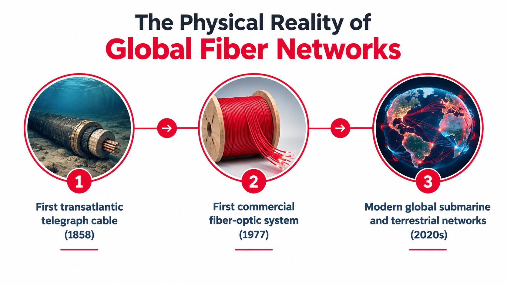
The Physical Reality of Global Fiber Networks
Global fiber networks are built from buried cable, pole lines, conduits, subsea systems, and equipment rooms. Their performance depends as much on route access, construction tolerances, skilled labor, and maintenance records as on optical transmission. A design that works on paper can still miss its service date if permits, make-ready work, material supply, or restoration access are unresolved.
Independent industry summaries reported that more than 5 billion kilometers of optical fiber had been deployed globally by 2020. Other estimates describe a terrestrial installed base of roughly 1.3 billion kilometers, while market summaries placed global installed fiber length above 1.2 trillion kilometers by the end of 2023. The totals differ because organizations count installed fiber in different ways. They still show the scale of the asset base and the number of physical decisions required to keep it available, as documented in this industry summary of fiber optic statistics.
The engineering breakthrough that changed the field
Modern fiber engineering developed around a demanding practical problem: retaining enough optical power for communication across useful distances. In 1966, Charles K. Kao identified that attenuation could be reduced below 20 dB/km for office-to-office communications, helping move optical fiber toward practical telecommunications. Corning produced single-mode fiber with 17 dB/km loss in 1970, and fibers with 0.47 dB/km loss were manufactured by 1976. That represented an improvement of more than 35-fold in attenuation performance within about a decade, according to this history of fibre optics.
Lower loss changed route economics and construction requirements. Engineers could plan longer spans, reduce regeneration requirements, and build around single-mode transmission. In 1988, TAT-8 became the first transatlantic fiber-optic cable, using 1.3-micrometer lasers and single-mode fiber. Its operation showed that undersea fiber could support reliable international traffic across ocean-scale distances, establishing a pattern that remains visible in subsea systems.
Capacity became the next constraint
As attenuation improved, engineering attention shifted toward carrying more information over dense, long routes. The first commercial fiber telecom test in 1977 carried live traffic at 6 Mbit/s. Later systems reached 10 Tb/s by 2001, 14 Tb/s over 160 km in 2006, 319 Tb/s over 3,000 km in 2021, and 301 Tb/s in a 2023 NICT result.
Those gains create field obligations. Route engineers must reserve duct space, protect spare fibers, place accessible handholes and closures, and schedule repair windows before construction begins. Permitting and labor availability can determine the delivery date as directly as optical design. Project stakeholders can browse network infrastructure opportunities to see where deployment capacity is required.
Practical rule: Treat every fiber route as a maintainable civil asset. Optical performance matters, but access, records, protection, and repairability determine whether that performance survives in the field.
Network Architecture and Design Principles
A useful network analogy is a municipal water system. Long-haul routes resemble transmission mains, metropolitan rings act like regional distribution, and access networks carry service to individual premises. Each layer uses fiber, but each layer has a different tolerance for distance, failure, construction disruption, and expansion.
Start with the physical hierarchy
The central office or core site is the aggregation point. From there, feeder routes move substantial fiber counts toward distribution areas, hubs, data centers, or remote cabinets. Distribution points divide the route into smaller service areas, while splice closures provide protected locations for joining cables, branching fibers, and managing restoration work.
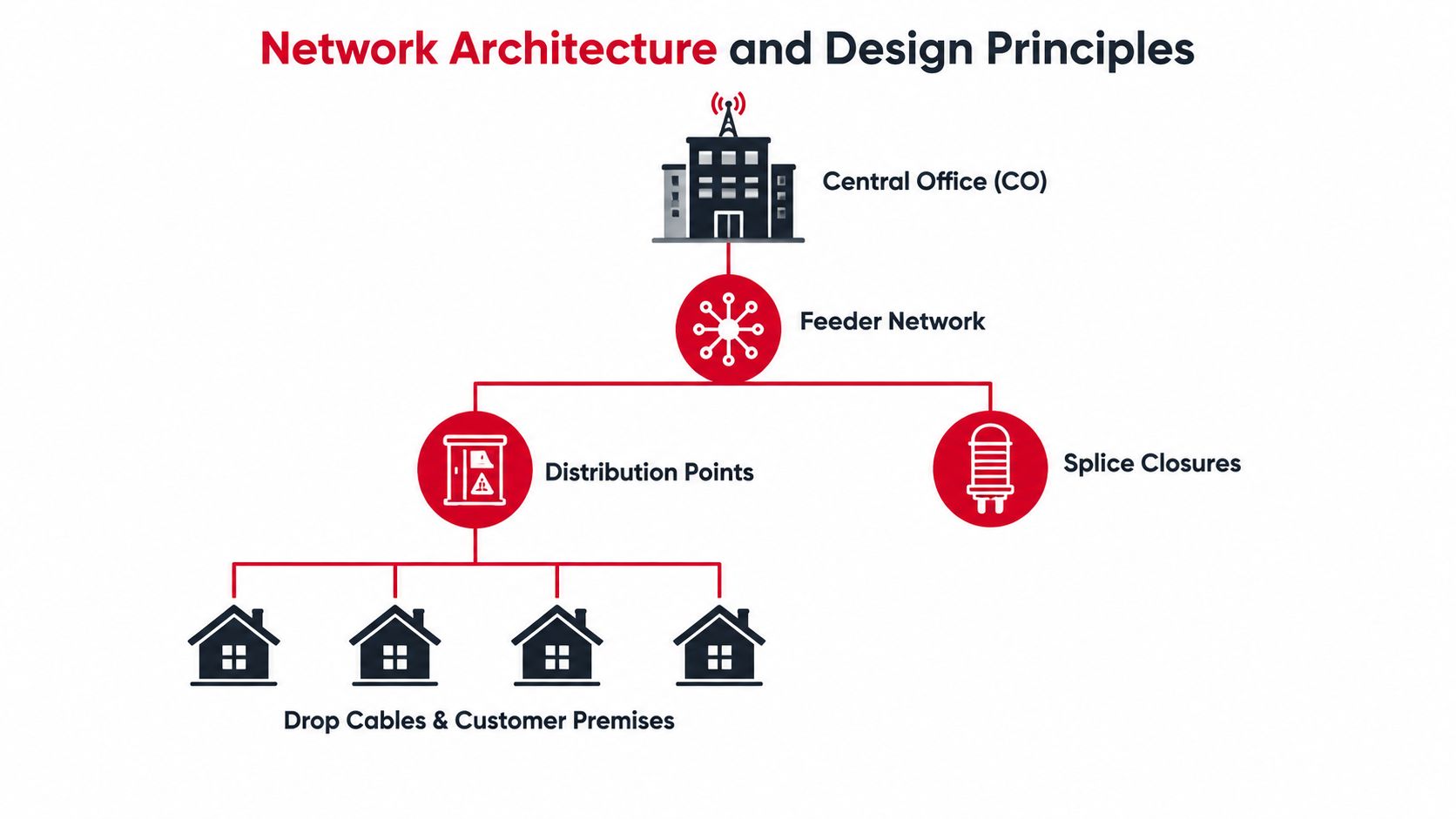
Long-haul backbone design prioritizes route diversity, low attenuation, controlled splice counts, and protection from major single points of failure. A metro ring adds geographic redundancy and connects central offices, carrier hotels, enterprise sites, and data centers. A last-mile network trades large route efficiency for many access points, customer drops, property constraints, and restoration demands.
Design for the failure you can actually repair
Redundancy isn't automatically useful. Two cables that follow the same bridge crossing or share one congested conduit may appear diverse on a diagram while remaining exposed to one physical incident. Engineers should map shared structures, crossings, handholes, pole lines, easements, and building entrances before they claim that a route is protected.
A practical design review asks:
- Route diversity: Can traffic reach the destination through a separate physical path?
- Access points: Can crews reach closures and cabinets without unreasonable traffic control or property coordination?
- Spare capacity: Does the cable and duct arrangement support future drops, reroutes, and repair requirements?
- Environmental protection: Will the selected cable, closure, conduit, and sealing approach withstand the installation and operating environment?
- Construction method: Does underground, aerial, or inside-plant work match the site constraints and maintenance plan?
Greenfield broadband construction usually emphasizes repeatable distribution, efficient customer connections, and scalable access points. An urban data center interconnect has different priorities. It may require extremely controlled entrance facilities, diverse building paths, short outage windows, and careful coordination with existing live systems. The same fiber type can serve both projects, but the civil design and risk profile are not interchangeable.
Capacity planning is a physical decision
Adding logical capacity later doesn't guarantee that the physical route can support it. A narrow conduit, crowded pole line, inaccessible handhole, or fully occupied splice tray can turn a routine expansion into a construction project.
Design principle: Reserve physical space before you need it. Spare duct, accessible structures, documented slack, and deliberate fiber assignment often cost less during initial construction than during an emergency expansion.
Route drawings should show more than a line between two endpoints. They should identify ownership boundaries, structures, crossings, splice locations, cable slack, access constraints, and restoration assumptions. A design that looks elegant in a network diagram can still be unbuildable if it ignores the street, the pole, and the property entrance.
Industry Standards and Performance Metrics
Optical budgets turn a conceptual route into an engineering test. They account for fiber attenuation, splice loss, connector loss, design margin, and the transmit and receive characteristics of the selected equipment. If the budget is too optimistic, a network can pass a basic continuity check and still fail under its intended operating conditions.
For standard single-mode fiber, ITU-T G.652 specifies maximum attenuation of 0.4 dB/km at 1310 nm, 0.35 dB/km at 1550 nm, and 0.35 dB/km at 1625 nm. Those limits make the 1550 nm and 1625 nm windows especially important for route design where low loss matters, while 1310 nm remains a significant operating window for standard single-mode systems. The attenuation values are specified in the ITU-T G.652 recommendation.
Read the standard as a design constraint
A route's theoretical fiber loss isn't the complete budget. Engineers must include every event that consumes optical power:
- Fiber span loss: Calculate the route length against the applicable attenuation value and operating wavelength.
- Splice loss: Count planned fusion splices and allow for the quality of the installed joints.
- Connector loss: Include patch panels, adapters, cross-connects, and equipment interfaces.
- Engineering margin: Retain enough allowance for aging, repair activity, measurement uncertainty, and future intervention.
- Wavelength compatibility: Confirm that cable, passive components, transceivers, and test equipment are specified for the same operating windows.
The standard's maximum attenuation figure shouldn't become a target for poor construction. A route can remain within a formal maximum while still wasting valuable budget through avoidable splice or connector losses. Clean end faces, correct preparation, sound closure workmanship, and stable test references matter because connectivity losses accumulate at discrete points.
Use metrics to evaluate proposals
Vendor proposals often emphasize cable count or headline capacity. A stronger review asks how the supplier calculated route loss, what splice assumptions were used, which wavelengths will be tested, and how the design will handle future repairs.
| Design question | Why it matters |
|---|---|
| What is the route length and fiber attenuation assumption? | It establishes the baseline optical loss. |
| Where are the splices and connectors? | Discrete events can consume more budget than the fiber span alone. |
| Which wavelengths are operational? | Loss and test results must correspond to the intended equipment. |
| What margin remains after installation? | A small remaining margin can limit maintenance and future upgrades. |
| How will results be handed over? | Untraceable test files make later fault isolation slower. |
The correct standard doesn't eliminate field variation. It gives the project team a shared acceptance framework. Design, procurement, construction, and commissioning should all use the same assumptions, otherwise each phase can appear successful while the assembled link fails to meet the operational requirement.
Construction Planning and Deployment Bottlenecks
Optical performance does not rescue a late build. In U.S. FTTH deployment, passings reached 98.3 million in 2025, while roughly 60 million potential first-time passings remain. Many of the most difficult routes are rural or constrained by permits, labor, and material availability, as described in coverage of U.S. fiber-to-the-home rollout challenges.
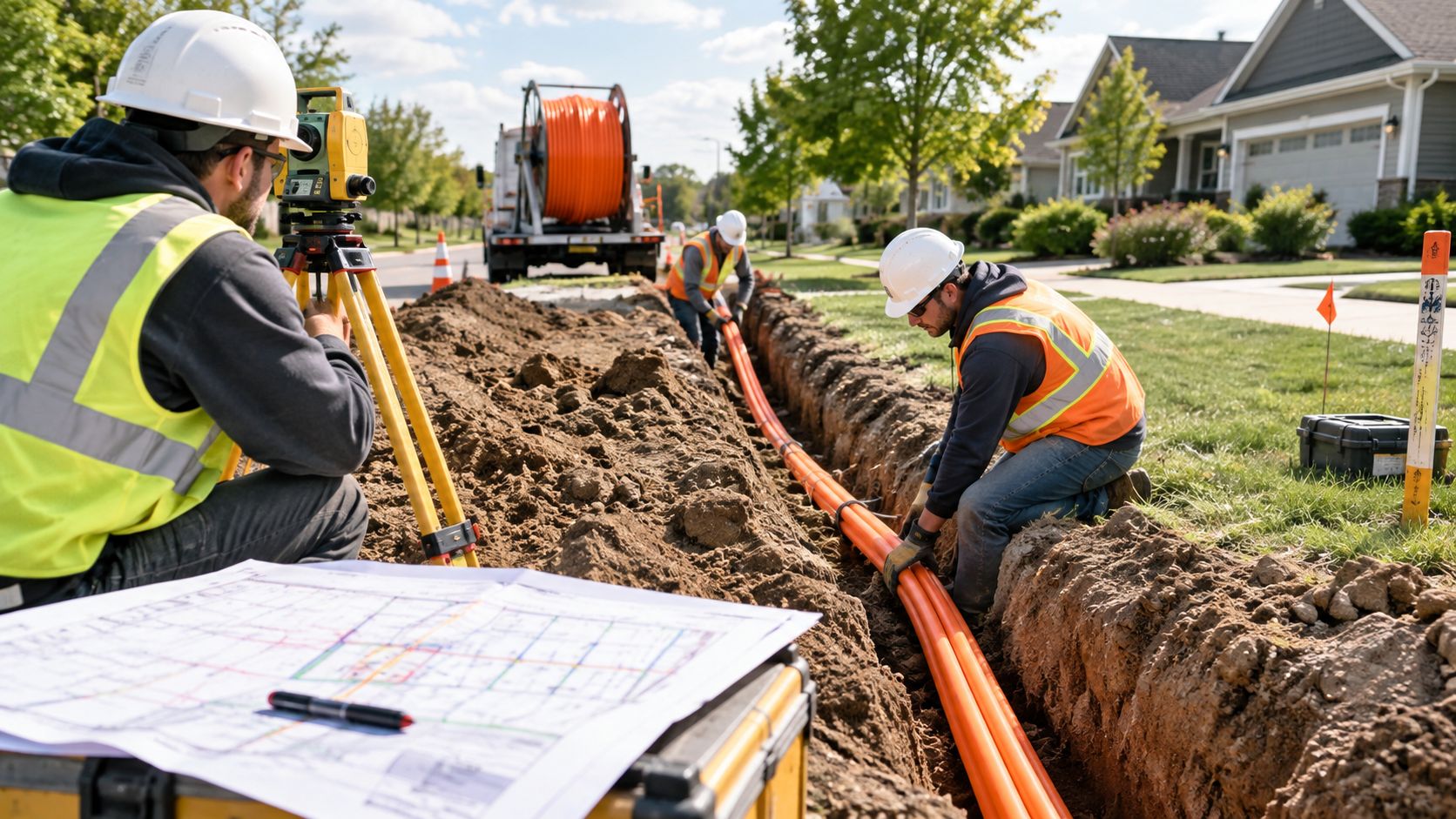
Schedules usually fail at interfaces between organizations. A permit may authorize the route but exclude a road crossing. A pole attachment agreement may be signed while make-ready work remains unfinished. A crew can have cable and splice materials on site yet lack safe truck access or an approved traffic-control plan.
Permitting creates sequence risk
Design completion is different from construction readiness. Drawings can be issued while agencies, utilities, railroads, municipalities, and property owners continue reviewing the work. Those dependencies determine whether crews can mobilize continuously or must move through fragmented sections.
Use practical controls to expose blockers early:
- Permit register: Track each jurisdiction, crossing, approval, condition, expiration, and responsible owner.
- Make-ready verification: Confirm poles, anchors, clearances, and existing attachments are ready before the fiber crew arrives.
- Utility coordination: Resolve conflicts with electric, communications, gas, water, and municipal assets before excavation or attachment.
- Access planning: Validate truck positions, restoration areas, lane closures, gated properties, and working hours.
- Material staging: Match cable, closures, cabinets, innerduct, handholes, and splice hardware to released construction segments.
Permit status must connect to the work package, not sit in a separate spreadsheet. A route that cannot be legally accessed is not a released construction segment.
Labor is a cost and capacity constraint
A 2025 supply-chain white paper estimated that labor accounts for 60–80% of deployment costs and that the industry needs to recruit and train about 180,000 workers for funding-driven build goals. The deployment labor challenge is covered in the same coverage of U.S. fiber-to-the-home rollout challenges. Approved engineering does not create field capacity. Qualified crews still must excavate, place cable, terminate, splice, test, restore surfaces, and produce acceptable records.
A workable schedule includes crew productivity, weather exposure, inspection time, restoration, rework, and specialist splicer availability. Assign one person to resolve field changes. Without that owner, a minor obstruction can remain open while several crews wait.
The video below provides additional field context for cable installation and site execution.
Field reality: The fastest design is one crews can build repeatedly, inspect safely, and hand over without a second construction campaign.
Testing Protocols and As-Built Documentation
Pulling cable doesn't prove that the link is ready. Acceptance requires evidence that the installed route has the expected continuity, loss performance, splice quality, and physical identity. Testing should begin with the project requirements, not with whatever results a technician happens to export at the end of the shift.
Build the test sequence around failure detection
A practical sequence moves from basic checks to detailed diagnosis.
- Inspect and clean interfaces. Connector end faces, adapters, patch panels, and test leads must be clean and suitable for measurement. Contamination can create misleading loss or reflectance results.
- Verify continuity and polarity. Confirm that each assigned fiber reaches the intended endpoint and that fibers haven't been crossed during splicing or termination.
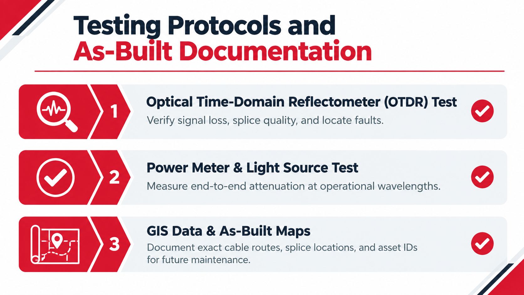
- Measure end-to-end insertion loss. Use a calibrated light source and power meter at the operational wavelengths specified by the design. This confirms the total attenuation through fiber, splices, connectors, and passive components.
- Run OTDR analysis. An Optical Time-Domain Reflectometer can show event locations, splice behavior, connector reflections, breaks, and unexpected route features. The trace is useful only when launch and receive conditions, pulse settings, range, and wavelength are appropriate.
- Resolve exceptions before handover. A failed result needs an owner, a corrective action, and a retest. Don't bury an exception in a large file package.
Make the records useful to the person on call
OTDR traces and power-meter results become operational tools only when technicians can connect them to the actual asset. Every record should identify the route, cable, fiber, endpoint, test direction, wavelength, instrument, date, and acceptance status. File naming should follow the operator's asset model instead of relying on a technician's personal convention.
As-built documentation should capture:
- Route geometry: Record the installed path, structures, crossings, entrances, and deviations from design.
- Splice information: Map closure IDs, tray positions, fiber assignments, and branch relationships.
- Asset identity: Associate cable, cabinet, handhole, closure, panel, and equipment identifiers with the GIS record.
- Depth and protection details: Document relevant installation conditions, conduit, innerduct, warning systems, and restoration notes.
- Handover exceptions: List unresolved constraints explicitly with an assigned action, not in informal email alone.
GIS accuracy directly affects repair decisions. If a fault trace points to a location that doesn't match the map, the response team loses time searching the wrong structure or route segment. Good documentation reduces uncertainty before the first outage occurs.
Handover standard: If the operations team can't locate the fiber, interpret the test, and identify the correct spare, the project isn't fully complete.
The AI and Data Center Impact on Fiber Engineering
AI-era data centers are changing fiber optic engineering priorities beyond traditional access-network expansion. The key question is no longer only how to connect more premises. It is how to move enormous volumes of data between compute, storage, switching, and adjacent facilities while managing density, power, latency, heat, and component availability.
In 2025, the datacom optical component market was forecast to exceed $16 billion, with more than 60% growth. The same coverage expected 800G transceiver shipments to double year over year and identified co-packaged optics and optical circuit switching as emerging architectural shifts, as described in this 2025 analysis of data-center optical interconnects. These are projections and market expectations, not guaranteed outcomes.
Density changes the design conversation
Traditional network planning often focuses on route length, attenuation, and customer reach. Data-center work adds a dense inside-plant problem. Engineers must coordinate structured cabling, patching, rack layouts, fiber distribution, equipment access, bend management, labeling, and expansion space inside facilities where small routing mistakes can affect many live connections.
High-speed optics also increase the importance of platform compatibility. The transceiver, fiber plant, connectors, polarity method, cleaning process, test equipment, and operating software must work as a system. A cable plant that performs adequately for one interface may not support the next architecture without changes to connector density, thermal management, or distribution design.
Supply chains now influence architecture
Independent reporting has warned that AI data-center demand is tightening fiber supply and creating bottlenecks for cable equipment and raw materials. That changes procurement from a late-stage purchasing task into an engineering input. Teams may need to qualify alternate assemblies, reserve manufacturing capacity, release long-lead items earlier, and preserve flexibility in optical module selection.
The right response isn't to buy blindly. It is to separate fixed requirements from adaptable ones:
- Fixed requirements: Required reach, interface compatibility, loss budget, environmental rating, and operational testing.
- Adaptable choices: Approved manufacturer, connector assembly, distribution hardware, and deployment sequence.
- Architectural options: Conventional pluggable optics, co-packaged optics, or optical circuit switching where the facility's operating model supports them.
- Verification gates: Sample testing, interoperability checks, thermal review, and documentation before broad deployment.
Metro networks serving data centers also feel this pressure. Diverse building entrances, scalable conduit, accessible meet-me rooms, and rapid restoration become strategic assets because the facility's demand can outgrow an access design that was adequate for ordinary enterprise traffic.
Executing Turnkey Infrastructure Partnerships
Fragmented contracting creates accountability gaps at exactly the points where fiber projects are most vulnerable. The designer may not own permitting, the construction contractor may not control splicing, the splicing team may not produce GIS records, and the testing contractor may inherit incomplete information. Each company can meet its individual scope while the owner receives a route that isn't ready for operations.
A turnkey structure assigns one accountable partner across the connected work. That doesn't mean every task must be performed by the same crew. It means design assumptions, field changes, construction quality, test results, and handover records move through one coordinated delivery process.
Connect design decisions to field execution
An end-to-end provider can align route selection with construction methods before drawings are finalized. For example, an aerial route needs pole surveys, attachment coordination, make-ready tracking, clearance checks, and safe access planning. An underground route needs utility research, potholing or equivalent field verification, excavation controls, conduit strategy, restoration planning, and structure placement.
The same coordination applies inside data centers. A provider that handles fit-outs can connect structured cabling layouts with equipment placement, pathway capacity, labeling, testing, and future expansion. This is different from installing cable after another party has fixed the rack and pathway decisions.
A project governance model should define:
- One technical baseline: Design drawings, bill of materials, route assumptions, optical budgets, and acceptance criteria stay synchronized.
- One change process: Field obstructions, owner requests, and material substitutions receive documented technical and commercial review.
- One quality trail: Inspection records, splice data, test files, punch lists, and as-built updates remain connected to the asset.
- One escalation path: The owner knows who resolves conflicts between permitting, construction, splicing, testing, and operations.
Choose partners by execution evidence
A provider's claims matter less than its handover package and field controls. Ask how it manages safety, crew qualifications, traffic control, restoration, splice quality, OTDR trace review, GIS validation, and emergency mobilization. For property owners evaluating fibre installation for property, the same principle applies, installation quality includes pathway planning, protection, termination, testing, and records, not just cable placement.
Southern Tier Resources provides a relevant model for this structure through its telecom infrastructure services. Its stated scope covers engineering, construction, fiber splicing, testing, documentation, wireline and wireless work, and data center fit-outs, with a safety-first operating model and 24/7 mobilization. Owners should still evaluate any provider against their specific route, standards, schedule, and acceptance requirements.
Turnkey delivery doesn't remove project risk. It makes responsibility visible. When one partner coordinates design, permitting, field construction, splicing, testing, and maintenance, the owner can identify the source of a failure without forcing separate contractors to negotiate responsibility after the fact. That clarity is especially valuable on projects where access constraints, labor availability, supply delays, or live-network cutovers can change the plan quickly.
Execution test: Select the partner that can explain how a design change becomes a controlled field instruction, a verified installation, and an updated as-built record.
Southern Tier Resources provides end-to-end fiber engineering, construction, splicing, testing, documentation, wireless infrastructure, and data center fit-out support for carriers, ISPs, facility operators, and enterprise teams. If your project needs one accountable team from route planning and permitting through commissioning and maintenance, visit Southern Tier Resources to discuss the deployment requirements.