At 10 p.m. in a data hall, the acceptance test rarely fails because a technician can't launch an OTDR trace. It fails earlier, when a connector end face gets mated with contamination that nobody documented. A fiber optic inspection scope gives the crew a repeatable view of that end face, then turns a vague “looks clean” judgment into evidence that can support a pass or fail decision.
The scope doesn't replace an optical loss test set or an OTDR. It controls whether those tests are being performed on a connector that's fit to test. That distinction matters on ordinary duplex links, and it matters even more on high-density MPO backbones where one overlooked fiber can complicate an entire acceptance package.
The Moment a Fiber Link Stands or Falls
A crew is pre-commissioning a 96-strand MPO backbone in a nearly finished data hall. The customer expects the room to cut over that night, and the project manager needs the sign-off package closed. Before certification begins, the lead technician fits the correct MPO tip to a probe-style inspection scope and checks the first trunk connector.
A faint smudge crosses zone B.
The connector looks normal from the outside, and the first test attempt has not failed. The inspection image still changes the decision. It provides objective evidence that the end face needs attention. The crew cleans the connector, inspects it again, and proceeds only after the result is acceptable. Skipping that gate could send technicians tracing unexpected loss or reflection through patch panels, cassettes, and reference cords for hours.

Why the image matters
Optical performance depends on the surfaces that mate. Contamination, scratches, and other defects can affect insertion loss and return loss. A trapped particle can also prevent proper physical contact. The IEC 61300-3-35 standard formalizes the inspection by dividing the end face into zones and defining the defects to examine.
That makes pre-test inspection a deployment gate, not a documentation exercise. The scope records the ferrule condition before mating, while an analyzer can apply the standard's pass/fail criteria consistently. Manual review may suit a low-volume LC job, but automated analysis helps maintain throughput on MPO links, where every fiber position must be assessed and recorded.
Field rule: If the connector hasn't passed inspection, the loss result isn't yet a trustworthy acceptance result.
The lead technician's action is straightforward. A passing image protects the link, the test equipment, and the handover record. A failing image stops the sequence. The crew cleans or replaces the connector, inspects it again, and establishes a new baseline before the condition becomes a commissioning dispute.
What a Fiber Optic Inspection Scope Actually Does
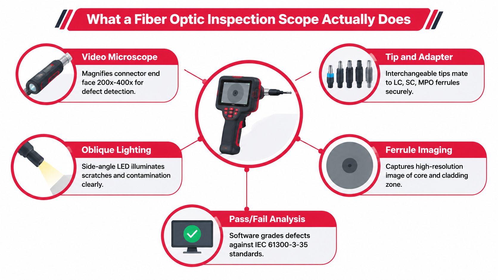
A connector can look clean and still fail inspection. A fiber optic inspection scope is a video microscope that examines the connector end face before mating. Its probe tip and connector-specific adapter align with the ferrule, illuminate the surface, capture the image, and send it to a display or analysis platform.
The scope provides more than magnification. Manual viewing lets a technician judge an enlarged end face, while an IEC-aligned system applies inspection zones, checks debris and scratches against defined criteria, and returns a pass or fail result. That difference affects field throughput. Manual review may be practical for a small LC job, but automated analysis gives crews a repeatable process when an MPO connector presents multiple fiber positions.
Three jobs the scope performs
It detects contamination and damage before mating. Dust, oil residue, particles, and scratches can be too small or poorly positioned for dependable unaided inspection. The scope exposes the end-face condition before one connector is pressed against another.
It supports a standards-based decision. The IEC 61300-3-35:2022 framework described by Fluke Networks treats inspection as a quantitative task. Automated analysis applies the same criteria to each connector, reducing differences between technicians and creating a clearer deployment gate.
It creates handover evidence. A saved image, result, connector identifier, and timestamp can accompany the OTDR trace and optical loss report. If a link later develops a problem, the record shows the connector's condition before mating.
The scope doesn't measure insertion loss or return loss. It does not replace an optical light source and power meter, an OLTS, or an OTDR. It comes before those tests because the physical interface must be inspected and, when required, cleaned before link performance is measured.
How IEC 61300-3-35 Shapes Pass and Fail Decisions
IEC 61300-3-35 turns an end face into defined inspection zones, so a pass or fail decision is based on defect location and size rather than on a technician's general impression. For a cylindrical ferrule, the inspection covers the mating contact area up to 250 µm in diameter. Rectangular ferrules require inspection across the full ferrule surface. The IEC publication for 61300-3-35 is the governing reference for the method and its revisions.
The zones run outward from the optical center. The core has the strictest criteria because a defect there can interfere directly with the guided signal. The surrounding cladding follows, then the adhesive region and outer contact area. Acceptance limits vary by defect type and zone, so the analyzer must be set for the connector geometry and applicable standard revision.
What the zones protect
- Zone A, core: The primary signal path. A scratch or particle here can scatter light at the most sensitive part of the interface.
- Zone B, cladding: The surrounding optical region. Defects can affect coupling, scattering, and repeatability, particularly on connectors that are repeatedly mated.
- Zone C, adhesive: The bonded area supporting the ferrule. Damage or contamination here may indicate a mechanical or structural problem, not a simple cleaning issue.
- Zone D, contact: The outer mating surface. A particle can prevent full seating, leave an air gap, or create unstable contact.
| Zone | Location | Scratches Allowed | Particles Allowed | Failure Risk |
|---|---|---|---|---|
| A | Core | No defects permitted under the standard's strict core criteria | No defects permitted under the standard's strict core criteria | Direct optical interference and elevated loss risk |
| B | Cladding | Limited according to the applicable standard criteria | Limited according to the applicable standard criteria | Coupling, scattering, and repeatability problems |
| C | Adhesive | Evaluated within the standard's defect classification | Evaluated within the standard's defect classification | Structural or ferrule-related concern |
| D | Outer contact area | More permissive than the inner zones, within the standard's limits | More permissive than the inner zones, within the standard's limits | Ferrule lift, air gap, and mating instability |
Inspection systems must detect 2 µm particles and 3 µm scratches. That requirement affects the entire imaging chain, not just magnification. The scope needs suitable optics, even illumination, stable focus, and analysis that can separate a real defect from glare, dirt on the adapter, or image noise.
On a live job, the result should drive the next action. A failed connector is cleaned and inspected again. If it still fails, the crew holds it out of service for repair or replacement rather than mating it and hoping the optical test will explain the result later. A scope that only enlarges the image cannot reliably classify the relevant defects or provide a defensible deployment gate.
Key Specs That Change Field Outcomes
A scope earns its place on a live job when its specifications support a clear inspection decision. Field of view affects how quickly a technician can frame a connector. Resolution, illumination, focus stability, and analysis determine whether the system can distinguish a small defect from glare, adapter contamination, or image noise.
The FOCIS FLEX product specification lists a 710 x 860 µm live field of view, 0.25 µm minimum manual detection capability, and less than 1.0 µm auto-analysis resolution. Another listed specification provides a 425 µm horizontal field of view and 0.5 µm minimum detectable particle size. These values are more useful for comparison than magnification alone because they connect directly to defect visibility and inspection speed.
Match the specification to the job
| Specification | Typical Value | Field Outcome |
|---|---|---|
| Field of view | 710 x 860 µm or 425 µm horizontal field, depending on instrument | A wider view frames more of the end face and can shorten a field inspection. A narrower view demands more careful positioning, particularly on arrays. |
| Manual detection capability | 0.25 µm on one listed specification | Fine manual resolution helps a technician examine borderline defects when focus and lighting remain controlled. |
| Auto-analysis resolution | Less than 1.0 µm on one listed specification | Automated analysis can identify small features consistently and apply repeatable classification rules. |
| Minimum detectable particle size | 0.5 µm on another listed specification | Detecting smaller particles gives the analyzer better visibility into contamination that could otherwise be missed. |
| Connector tip compatibility | Connector-specific | LC, SC, UPC, APC, and MPO work require the correct tip and stable ferrule alignment. |
| Focus and calibration | Instrument-dependent | Reliable focus prevents a blurred edge from being mistaken for a defect or a real defect from being overlooked. |
Magnification does not determine suitability by itself. Inspection scopes are commonly discussed across the 100x to 400x range, while the practical choice depends on connector type, field of view, image resolution, and automated analysis capability, as noted in market guidance on fiber inspection scopes.
For a quick LC sweep, a wider field and fast autofocus can improve throughput. For IEC 61300-3-35 acceptance, the analyzer's ability to resolve and classify defects matters more than a dramatic zoom setting. Manual review gives technicians control over borderline images, while automated analysis improves repeatability across a busy crew. The trade-off is setup and verification: automation helps only when the correct tip, focus, calibration, and analysis rules are in place.
MPO work adds alignment pressure. The tip must hold the array squarely, and the image must cover the relevant ferrule surface without leaving outer fibers outside the inspection area. A specification that looks strong on a single-fiber connector may still produce slow or incomplete inspections on an MPO link.
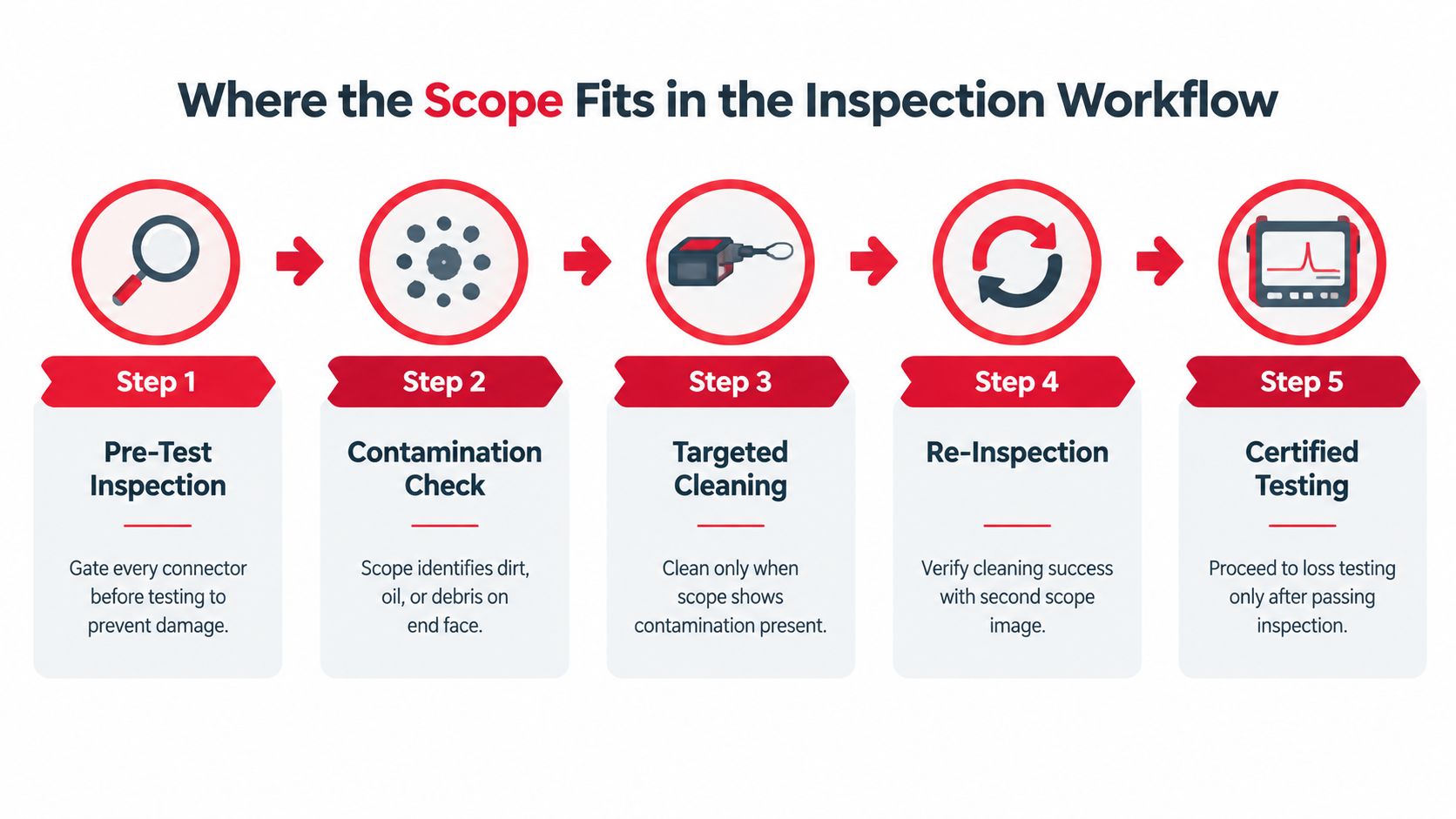
Where the Scope Fits in the Inspection Workflow
A fiber link can fail before the first test lead is connected. Inspection is the deployment gate that protects the connector, reference interfaces, and measurement that follows. The sequence should be applied to both sides of the connection.
Pre-test inspection: Inspect the connector under test, its mating connector, and the reference equipment interfaces before mating anything. The IEC 61300-3-35 standard supplies the framework for evaluating the end face and applying pass or fail zones.
Contamination decision: Stop if the image shows debris, oil, residue, or a suspected defect. Mating a questionable connector to see whether the test passes can contaminate the other interface and compromise the measurement.
Targeted cleaning: Clean when inspection identifies contamination or when the procedure requires it. Cleaning an uninspected surface can spread debris, leave residue, or make the crew assume the interface is ready without evidence.
Re-inspection: Capture another image after cleaning. Release the connector only when the new image supports a pass decision.
Certification testing: Start OLTS, power-meter, or OTDR work after the interface passes inspection. The scope does not measure link loss, reflectance, or length. It establishes a known physical condition before those measurements begin.
Reinspect after connector events
A connector can pass inspection before installation and fail after routing, handling, or mating. Inspect again after disconnecting and reconnecting it, after suspected contamination, and during maintenance work that disturbs the link.
The same discipline protects reference cords. A dirty device-side connector can transfer contamination to a reference interface during testing. That cord may then carry the problem to later links, affecting subsequent measurements. Stored inspection images make the sequence easier to audit and help separate a connector problem from a test-equipment problem.
The field record should identify the connector, test location, inspection result, cleaning action if performed, and related OTDR or OLTS file. Together, these records connect physical end-face condition with measured performance and give the commissioning team a defensible test trail.
The short training video below shows inspection practice and equipment handling.
Pre-Test Inspection on LC and MPO Connectors
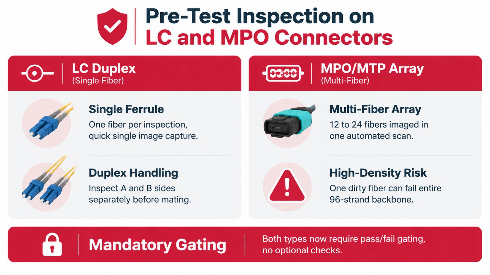
LC and MPO connectors require the same pass/fail discipline, but the inspection task changes with the connector format. An LC exposes one fiber end face in a compact ferrule, so the technician can usually center the image, check the IEC 61300-3-35 zones, and save a result quickly. Duplex LC assemblies still contain two inspection points. A clean A side does not verify the B side.
MPO and MTP assemblies place multiple fiber positions in one ferrule. The technician must select the correct tip, align the ferrule, and confirm that the complete array is visible. A sharp image is not enough if an outer position falls outside the field of view or the analysis skips part of the end face.
LC work favors speed, MPO work favors control
LC inspection usually rewards a fast, repeatable sequence:
- Select the connector tip: Fit the adapter that matches the connector geometry and polish type.
- Center the ferrule: Keep the end face square and fully inside the image.
- Run the analysis: Save the pass result, or record the cleaning action when contamination causes a failure.
- Repeat on the mating side: Inspect both connectors as separate points.
MPO inspection often benefits from automated analysis because one image contains several fiber positions and inspection zones. Manual grading takes longer and can vary between technicians when cores, cladding regions, alignment features, and contamination appear together. Automation improves repeatability and throughput, provided the scope supports the MPO configuration installed on site, including the correct male or female interface and any recessed access arrangement.
A narrow field of view can work well for one LC ferrule and still leave an MPO array partly unverified.
Manual analysis remains useful for unusual connector conditions or when the automated result needs review. The trade-off is time and consistency. The same portable scope can cover LC and MPO work when it has the required interchangeable tips and inspection formats. For crews moving between patch panels, trunks, cassettes, and equipment ports, tip coverage belongs in the purchase decision.
IEC 61300-3-35 evaluates the inspected contact area, so the deployment gate applies to the complete connector. An MPO should not pass because its center fibers look clean while outer positions remain outside the image or analysis. Store the full result before mating, then proceed to link testing only after every required position has been assessed.
Connecting Inspection to OTDR and Link Loss Budgets
An inspection image and an OTDR trace answer different questions, but they belong in the same fault investigation. The image asks whether the connector surface was clean and undamaged before mating. The trace asks where the optical event appears and how the link behaves along its length.
A contaminated end face can create a loss event, a reflective event, or an unstable result that changes after the connector is disturbed. An OTDR may show a step in the trace or a reflective peak at the connector location. The scope helps the technician decide whether the physical interface offers a credible explanation before replacing modules, reopening splice closures, or retesting an entire backbone.
Use the artifacts together
When a link approaches its allowed loss budget, the inspection record becomes more valuable. A total result near the limit can come from several contributors, so the technician needs to separate connector condition, splice performance, fiber attenuation, and test setup. A passing image doesn't prove that the link will pass loss testing, but a failing image tells the crew to correct a known interface problem before interpreting the test result.
Document the relationship in the job record:
- Identify the interface: Record the panel, port, cassette, trunk, or equipment location.
- Attach the end-face image: Keep the inspection result with the connector identifier.
- Store the OTDR trace: Mark the corresponding event location where the test system allows it.
- Record the loss result: Include the OLTS or power-meter result and the applicable acceptance limit.
- Note corrective action: State whether the crew cleaned, replaced, remated, or escalated the connector.
A technician should also inspect the opposite end and relevant reference interfaces when a trace shows an unexpected event. The visual evidence can't prove causation by itself, but it narrows the investigation and prevents the team from treating an optical waveform as an isolated file.
For DWDM and other links with tight performance margins, that discipline matters even more. The closer the measured result is to the engineered budget, the less room there is for an unexamined connector defect or a contaminated test interface.
Field Checklist for Choosing and Using a Scope
Choose the scope around the connectors, link types, and acceptance process your crews handle. A model suited to LC patching may lack the probe access, field of view, or automated array analysis required for MPO trunks. Magnification alone does not correct poor alignment, uneven illumination, or software that leaves the pass decision to the operator.
Selection checklist
- Standards analysis: Use automated pass/fail analysis aligned with IEC 61300-3-35 when the project requires repeatable acceptance decisions.
- Connector coverage: Confirm support for the LC, SC, UPC, APC, and MPO or MTP configurations installed in the plant.
- Resolution and field of view: Select a live view wide enough for efficient framing, then confirm that the system resolves the defect sizes specified by the inspection procedure. The FOCIS FLEX specifications show why both measures belong on the comparison sheet.
- Handling and access: Check probe reach, tip locking, display readability, battery operation, and access inside dense panels or recessed ports.
- Reporting: Verify that the instrument exports inspection images and results in formats that can remain with OTDR and OLTS files in the acceptance package.
- Procedure alignment: Map the scope routine to the project quality plan and documentation requirements, including applicable ISO/IEC 14763-3 provisions.
Crew-use checklist
Before testing, inspect the connector under test, its mating connector, and the reference interfaces. A failed image requires cleaning with the approved method, followed by another inspection.
During testing, stop after an unexpected loss or reflection event and inspect the connector before changing test settings. A link can produce an acceptable measurement while a zone A defect remains, so the visual result still requires action.
After testing, inspect connectors that were disconnected, moved, or remated. Archive the final images with the trace and loss report. The next technician should be able to follow the evidence without relying on memory.
The common failures are procedural. Crews skip inspection between mating cycles, depend on magnification without automated grading, inspect only the easiest MPO fibers to view, or save traces without the end-face images needed to investigate an unexplained result. A defined scope routine closes those gaps and makes inspection a deployment gate before testing proceeds.
Southern Tier Resources incorporates fiber inspection scopes into fiber testing and documentation workflows. Its technicians use the magnified end-face view to identify dirt, debris, and scratches before connectors are accepted. For inspection-led fiber testing, splicing, and infrastructure documentation, visit Southern Tier Resources.