The commissioning team has energized the first high-density cabinets. Breakers hold, the UPS is stable, and the room looks ready for turnover. Then a thermal scan finds one hot parallel conductor, the PDU neutral runs warmer than expected, or an A feed shares a tray segment with its supposedly independent B path. The cable installation passed a paper review, yet the live system has exposed the weakness.
That situation is becoming harder to avoid as AI equipment raises rack demand and introduces more complex electrical behavior. Data center power cables are no longer a commodity line item. They're part of the thermal model, the power-quality model, the redundancy plan, and the maintenance record. A sound design starts with the environment and the actual load, then uses ampacity tables as one input rather than the final answer.
Why the Cable Plan Decides the Room
A commissioning walkdown often reveals problems that drawings conceal. A feeder can pass continuity and insulation checks while its infeed current drifts under load. A redundant rack can have two labeled whips that enter the same congested tray, share a sleeve, or terminate in equipment with a common upstream dependency. The breakers may remain closed while the intended fault tolerance has already disappeared.
The first AI cluster makes these weaknesses visible quickly. Server power supplies and UPS equipment can produce distorted current, and a neutral that looked lightly loaded during a balanced-load review may carry substantial harmonic current. If the design team only checked phase balance and nominal breaker ratings, the acceptance test becomes the first serious power-quality investigation.
Practical rule: Treat every cable schedule as an operational document, not a procurement list.
That means recording the actual installation conditions before the run is released. Tray fill, loaded conductor count, ambient temperature, insulation rating, terminal limits, routing, and future circuit allowances belong in the design record. The sizing power distribution for racks guidance from E & I Sales is a useful reference for connecting rack demand to the distribution equipment that serves it, but the final cable decision still depends on the installed environment.
Redundancy exists only where the conductors are independent
An A and B topology is meaningful only when the paths remain separate through the parts of the installation that can fail. Separate UPS sources don't compensate for a shared cable tray bottleneck, a common conduit sleeve, or a rack whip that was connected to the wrong panel. Labeling errors create the same risk as physical commonality because maintenance staff may isolate what they believe is one path and accidentally interrupt both.
The cable plan also controls future work. Adding circuits to an existing tray can reduce available ampacity even when the facility voltage and breaker ratings haven't changed. A room that looks acceptable at initial turnover can become thermally marginal after expansion if the original schedule didn't preserve usable capacity.
The right test is therefore not, “Did the cable meet the table?” It's, “Will this cable remain within conductor and termination limits during the hottest, most heavily loaded, most harmonically demanding operating condition the room is expected to see?” That question keeps reliability ahead of a narrow code minimum.
Cable Types, Ratings, and Where Each One Belongs
Start at the utility entrance and follow the power path physically. Medium-voltage feeders bring energy into the facility or between major electrical rooms. Transformers step that supply down for low-voltage distribution, and large feeders then carry power toward switchboards, UPS systems, PDUs, or busway tap-off points. Near the rack, the installation becomes more granular, with whips and branch circuits feeding rack power distribution units.
Conductor material comes first, but insulation and installation method complete the selection. Copper offers familiar termination behavior and strong mechanical handling characteristics. Aluminum can reduce conductor mass and material demand, but it requires disciplined preparation, compatible terminals, appropriate joint compound where specified, and careful attention to torque and long-term connection behavior.
XHHW-2 is common in feeder work because its insulation system supports demanding wet and dry locations when the complete cable and installation method are listed for that use. EPR insulation appears in applications where flexibility and medium-voltage performance matter. The jacket or assembly rating answers a different question. TC-ER can suit listed industrial cable tray applications with the required protection and support, LSZH can be selected where smoke and halogen performance are priorities, and armored MC cable often fits compact whips or protected vertical transitions.
A 90-degree insulation rating doesn't automatically permit operation at 90 degrees at the termination. The conductor, insulation, lug, breaker, switchgear, and equipment terminals each impose limits. The usable design capacity is constrained by the lowest applicable limit, not by the most favorable number printed on the cable jacket.
Follow the ladder, then verify the listing
A medium-voltage feeder may need shielding, stress control, grounding, and termination kits that have little in common with a rack whip. A busway system shifts part of the distribution problem from long cable pulls to housing, joints, plug-in units, and manufacturer-specific installation controls. A branch circuit may be short, but its bend radius, connector retention, labeling, and terminal temperature still affect the final result.
| Cable family | Typical use | Key rating to track |
|---|---|---|
| Medium-voltage shielded cable | Utility, transformer, and primary distribution paths | Voltage class, insulation system, shield and termination requirements |
| XHHW-2 conductors | Low-voltage feeders and branch circuits in approved raceways or cable assemblies | Ampacity, insulation temperature, wet-location listing, terminal limits |
| EPR cable | Medium-voltage or demanding flexible distribution applications | Voltage class, insulation performance, bending and termination requirements |
| TC-ER cable | Listed tray runs and industrial-style distribution paths | Tray listing, ampacity, support, jacket and exposure limits |
| LSZH cable | Areas with controlled smoke and halogen requirements | Listing, flame performance, smoke characteristics, installation method |
| Armored MC cable | Whips, protected drops, and vertical risers | Armor, grounding path, bend radius, connector compatibility |
| Busway tap-off cable or whip | High-density distribution from busway to PDU or rack | Tap-off rating, connector listing, temperature and mechanical support |
For adjacent applications, the practical explanations in this solar and EV cable advice resource from AdVoltage Electrical can help clarify how conductor selection, installation method, and three-phase behavior interact. Data center work still requires its own listed assemblies, code review, and equipment coordination.
Sizing for Ampacity in a Hot, Harmonic-Rich Floor
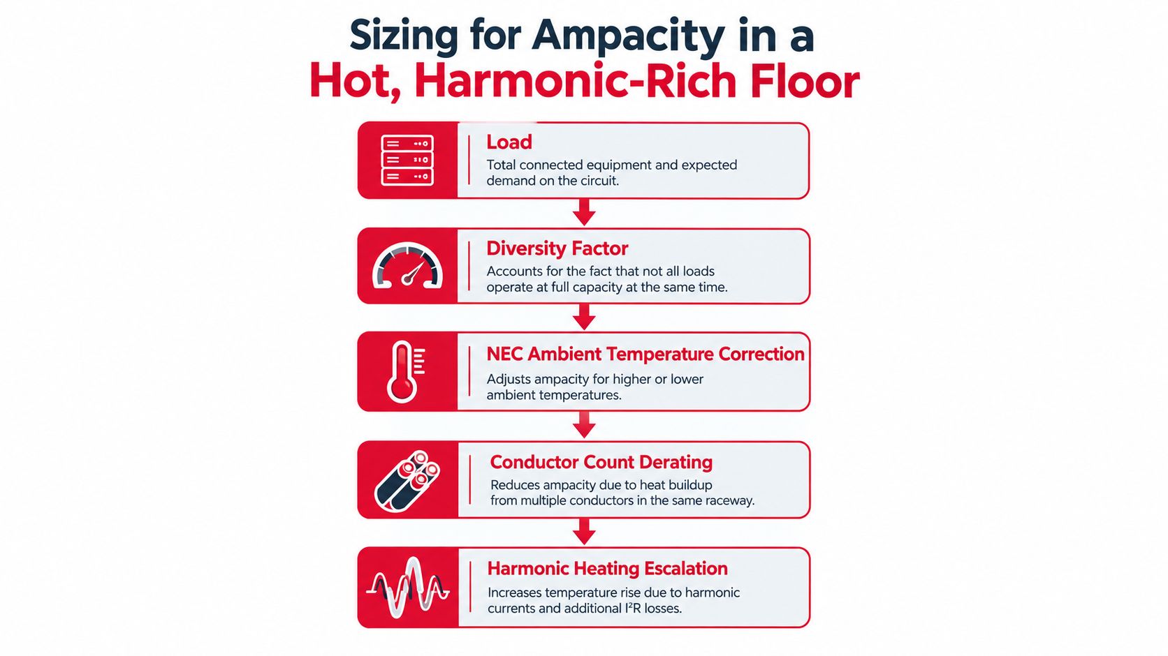
Ampacity is a thermal calculation. The basic sequence starts with the load, applies the expected diversity, and then applies correction and adjustment factors for ambient temperature and multiple current-carrying conductors. The NEC tables generally use a 30°C ambient reference, so the table value is only a starting point when conductors run through a hot-aisle environment, a tightly packed tray, or a route beside energized circuits. IAEI's data center electrical guidance describes the need to account for actual thermal conditions rather than relying on tabulated ampacity alone.
Hot-aisle containment can raise the surrounding temperature. Tray congestion can restrict heat dissipation. Adjacent circuits add another heat source. The designer must also check whether the termination is rated for the conductor temperature being used in the calculation. If the cable can tolerate a higher insulation temperature but the lug or breaker terminal cannot, the terminal limit controls the usable ampacity.
Harmonics change the neutral calculation
Switch-mode power supplies in servers and UPS equipment draw distorted current. Triplen harmonics, especially the third harmonic and its multiples, are in phase on all three phases. They add in the neutral instead of canceling, so a feeder that appears balanced by phase current can still have a heavily loaded neutral and a localized thermal problem. NFPA 70 data center guidance is relevant when the design team reviews conductor ampacity, neutral treatment, and protective-device coordination.
The response may require a four-wire-plus-ground arrangement or a separately sized neutral based on the calculated harmonic spectrum. Phase balancing alone doesn't solve triplen-harmonic loading. Parallel conductors also need equal impedance and correct phase grouping, because unequal sharing can create a hot leg even when the total feeder current appears acceptable.
AI density makes the envelope less forgiving. Reported AI rack loads of 30 to 80 kW, compared with approximately 5 to 15 kW for traditional workloads, are documented in industry cable-selection analysis. That contrast isn't a reason to choose the largest available cable automatically. Installation method, bundling, ambient heat, harmonic spectrum, emergency loading, and future rack deployment determine whether a larger conductor actually solves the problem.
Before procurement, demand these inputs:
- Load profile: Continuous, peak, emergency, and expected future operating conditions.
- Thermal environment: Design or measured ambient temperature, containment arrangement, tray fill, and neighboring circuits.
- Conductor arrangement: Number of loaded conductors, parallel sets, phase grouping, neutral treatment, and grounding path.
- Power quality: Expected or measured THD, UPS mode, PDU input design, and representative high-utilization measurements.
- Equipment limits: Insulation rating, lug rating, breaker terminal temperature, and protective-device settings.
- Validation plan: Thermal modeling or field verification, torque records, infrared scans, and acceptance measurements.
A cable is correctly sized only when those conditions remain inside the thermal and electrical limits throughout the operating envelope.
Connectors, Standards, and the A and B Feed Topology
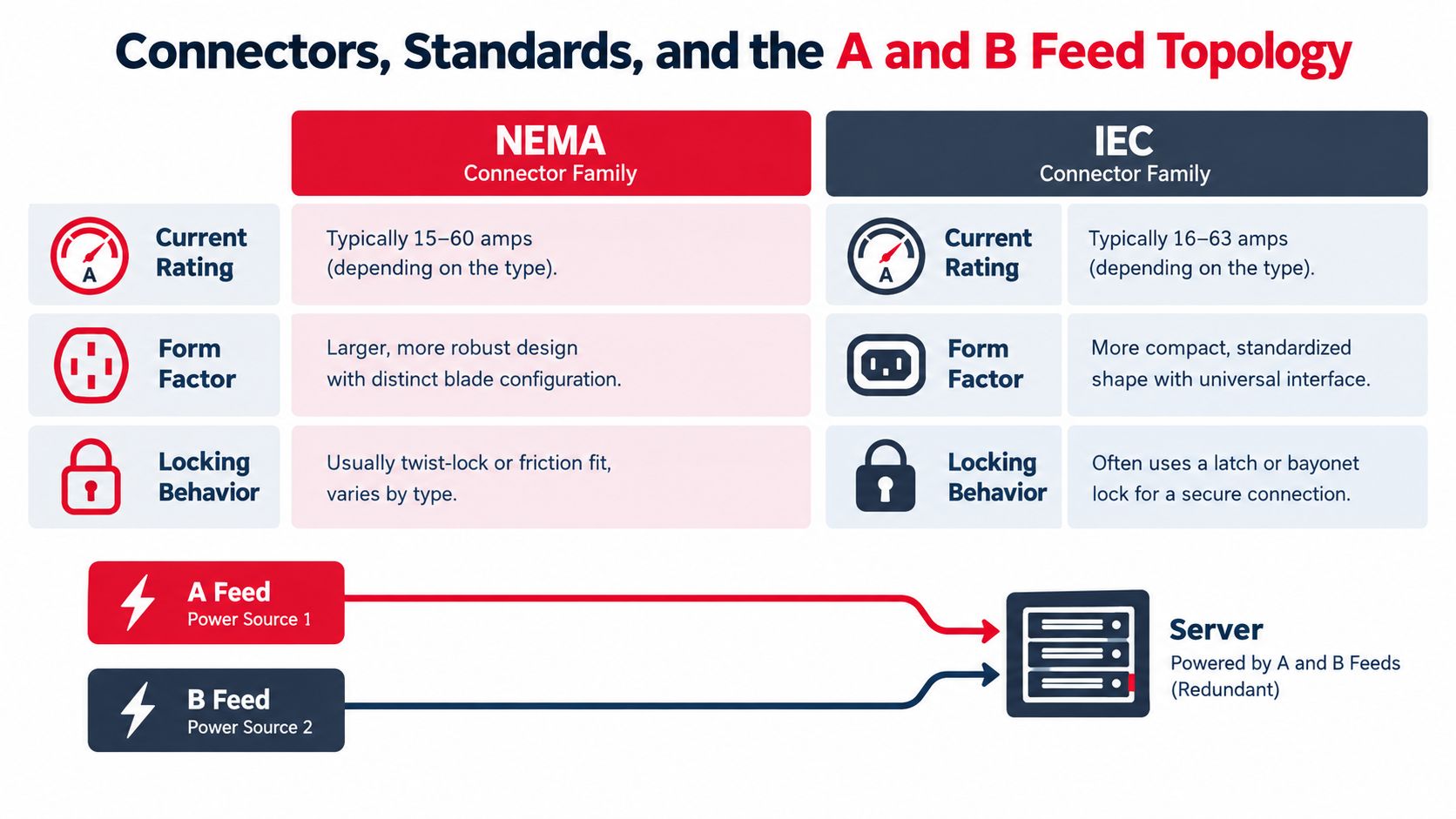
The connector is where a carefully calculated cable meets a human-accessible interface. NEMA and IEC families offer different form factors, current ranges, keying arrangements, and locking behavior. The selection should reflect the equipment inlet, the expected service work, and the consequences of accidental removal or incomplete engagement.
NEMA devices are familiar in many North American installations and cover a broad range of straight-blade and locking configurations. IEC connectors are common in rack equipment and modular power distribution, where compact form factors and retention features can simplify dense cabinet layouts. Neither family is automatically safer. The listing, mating compatibility, retention method, environmental exposure, and maintenance access matter more than the label on the connector family.
A and B means separate paths, not two labels
A resilient topology carries the load through two independently maintainable paths. The paths may originate from diverse transformer and UPS sources, feed separate PDU enclosures, and terminate at separate rack-mounted infeed PDUs. The rack equipment must support the intended dual-cord behavior, and the facilities team must be able to isolate one path without removing the other.
Busway can replace many long whips in high-density rooms. It offers flexible tap-off locations and can simplify expansion, but the joints, plug-in units, covers, and tap-off connections become critical inspection points. Long cable runs offer different advantages, including familiar raceway practice and broad equipment compatibility, but they can consume tray space and make late rack moves labor-intensive.
Common redundancy failures include shared tray segments, common conduit sleeves, mislabeled grounding conductors, and PDU designs that share a neutral or bus. A connector change won't repair a topology defect. For teams also coordinating communications, detection, and safety interfaces, a review of Molex fire and security solutions from Amax Fire & Security Ltd. can provide useful context on connectorized infrastructure, though power-feed selection still requires electrical equipment listings and project-specific engineering.
| Option | Typical rating | Redundancy behavior | Best fit |
|---|---|---|---|
| Locking NEMA connector | Equipment and circuit dependent | Supports retention when correctly matched and installed | Enterprise rooms with familiar North American service practices |
| IEC rack connector | Equipment and assembly dependent | Compact dual-infeed arrangements can support A and B rack feeds | Dense cabinets and standardized rack deployments |
| Busway with tap-off | System and tap-off dependent | Separate busway sections can support independent paths | Expandable high-density halls with planned tap-off coordination |
| Dedicated feeder and whip | Cable and protective-device dependent | Independent routes can preserve path separation | Rooms requiring custom routing or varied cabinet layouts |
Choose the connector and topology together. Replacing a connector after cabinets arrive can force changes to whips, PDUs, labels, spares, and acceptance documentation.
Installation Practices That Decide Day-Two Reliability
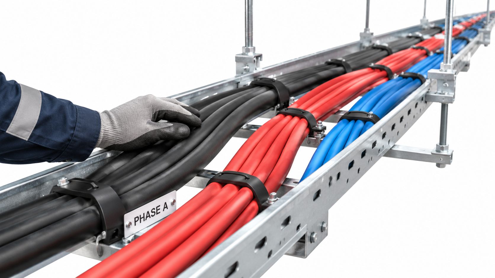
The crew needs more than a cable schedule. Before pulling, confirm the manufacturer's minimum bend radius, pulling tension, pulling lubricant compatibility, and the transition details at every tray, conduit, switchgear, transformer, and PDU entry. A cable that fits electrically can still be damaged by a tight turn or a poorly supported riser.
Parallel conductors deserve deliberate layout. Keep each phase grouping consistent, maintain equal path length where the installation requires it, and verify that conductors don't split across different magnetic or thermal paths without engineering approval. Unequal impedance encourages unequal current sharing, while poor grouping can create avoidable heating and interference.
Install for the next outage, not just today's pull
Support cables according to the listed system and project requirements. Keep power and communications cabling separated as required by code and the equipment manufacturer, maintain clean tray lanes, and avoid tie patterns that crush jackets or block inspection. If a future circuit is likely, reserve practical tray and conduit capacity before the room is full. Upsizing a conduit can be sensible, but it doesn't replace a documented thermal review of the future conductor count.
At terminations, use a calibrated torque tool and record the result. “Tight by feel” isn't a commissioning method. Aluminum terminations deserve particular attention to preparation, oxide control, joint compound where required, lug compatibility, and retorque instructions from the equipment manufacturer.
Label both ends, long tray runs, each conductor in a parallel set, and every transition that could confuse a technician. The as-built package should identify cable routes, phase grouping, source and destination, termination records, test results, and any approved field changes. A redline left on the wall isn't an asset record.
Clean routing is a reliability control. It makes heat, damage, misidentification, and unauthorized changes easier to see.
Testing, Commissioning, and Routine Maintenance
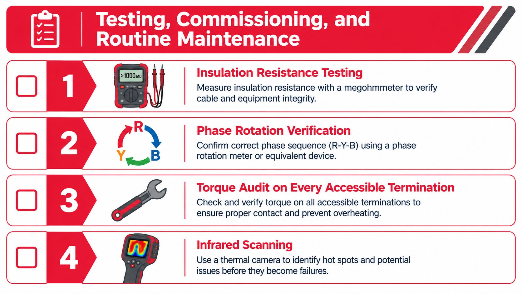
Testing should prove the cable's installation, not merely confirm that a meter can find continuity. Begin with insulation resistance testing using a method and test voltage appropriate to the equipment and cable system. Record the results by circuit, phase, neutral where applicable, and grounding conductor, then compare them with project acceptance criteria and manufacturer requirements.
Verify phase rotation before connecting three-phase loads. A correct voltage reading with incorrect rotation can still damage equipment or create an operational fault when motors, UPS inputs, or phase-sensitive equipment are energized. Audit every accessible termination with a calibrated torque tool, especially after equipment installation or any work that disturbed the connection.
Test the neutral under the load that matters
Infrared thermography under load can expose loose lugs, unequal parallel-conductor sharing, overloaded neutrals, and poor busway joints before a protective device operates. Capture the operating condition, ambient conditions, load level, and equipment identity with each image. A cool scan at light load doesn't prove the connection will remain cool during a high-utilization period.
Power-quality measurements belong in the same acceptance sequence. Measure phase and neutral current at representative IT loads, including high server-utilization conditions. The purpose is to document harmonic behavior while changes are still accessible. A phase-current balance review alone can miss a neutral that is heating from triplen harmonics.
A practical record set includes:
- Insulation results: Circuit identity, test method, readings, and acceptance status.
- Rotation results: Source, destination, phase sequence, and corrective actions.
- Torque records: Terminal identity, tool calibration status, measured value, and technician.
- Thermal images: Load condition, image location, temperature observations, and follow-up.
- Power-quality data: Phase current, neutral current, operating mode, and representative IT utilization.
- As-built evidence: Route, conductor arrangement, source, destination, labels, and approved deviations.
Routine maintenance should respond to operating conditions and work history. Re-scan after major load changes, recheck connections after equipment replacement or disturbance, and investigate any new neutral-current or thermal trend rather than waiting for a breaker trip. Keep the records with the asset so the next facilities team inherits a measured system instead of a guess.
Choosing Materials, Voltage, and Topology for the Long Run
The copper-versus-aluminum decision is only useful when it includes the whole installation. Compare material availability, conductor handling, termination labor, joint compound requirements, bend radius, spare capacity, replacement logistics, thermal losses, and the consequence of an outage. A lower purchase price can disappear if the project needs specialized terminations, extra preparation, difficult bends, or more restrictive maintenance procedures.
Aluminum can make sense on large, accessible feeders where its weight and material requirements simplify the pull and the project can enforce disciplined termination practice. It loses its advantage when crews lack compatible tooling, the route demands tight bends, replacement stock is uncertain, or the equipment interface has limited space. Copper can be easier to handle and terminate in many low-voltage applications, but it isn't automatically the lowest-risk choice in every large distribution path.
The decisive issue is often workmanship. An aluminum feeder with correct lugs, preparation, torque control, inspection, and documented maintenance can be dependable. A copper feeder with poor bend control, loose terminations, or undocumented parallel grouping can fail. Material selection must therefore be tied to the crew capability and the facility's long-term maintenance model.
AC and DC are different risk profiles
Conventional 415-volt AC distribution remains familiar to designers, inspectors, operators, and equipment manufacturers. It integrates with established switchgear, transformers, UPS systems, PDUs, protective devices, and rack equipment. Its drawbacks include conversion stages, phase and neutral management, and the need to coordinate AC protection and arc-flash behavior across the distribution path.
Emerging 800-volt DC architectures can reduce current and conductor requirements for the same power, but they move complexity into high-voltage DC protection, conversion equipment, arc-flash analysis, isolation, switching, and interoperability. A DC architecture must also have a mature equipment ecosystem and clear maintenance procedures. It isn't a simple cable substitution.
The scale pressure is real. Recent analysis forecasts 2025 data center electricity demand growth of 17 percent, with total consumption potentially doubling by 2030 and AI-focused consumption tripling; the same IEA analysis cites another forecast for roughly 850 to 900 kilotonnes of copper- and aluminum-based data center cable and related metallic products in 2026, about 25 percent above 2025 levels. Those are projections, not a reason to select a particular voltage or conductor without a site-specific lifecycle comparison.
A project decision framework
Before locking the specification, answer four questions:
- What load envelope must the system survive? Include present demand, future rack deployment, emergency operation, synchronized workload behavior, ambient temperature, harmonic current, and neutral loading.
- Which topology preserves maintainability? Compare dedicated feeders, busway, and hybrid layouts by path separation, inspection access, tap-off flexibility, spare capacity, and outage consequences.
- Can the installation team control the selected material? Confirm compatible lugs, preparation methods, torque tools, joint compounds, bend space, replacement stock, and training before choosing aluminum or copper.
- Does the voltage architecture fit the ecosystem? Check protection, conversion, arc-flash procedures, equipment compatibility, interoperability, commissioning capability, and the operator's ability to maintain the system safely.
The safest cable isn't necessarily the largest conductor or the newest architecture. It's the one whose thermal, harmonic, mechanical, protection, and maintenance assumptions remain true after the room is occupied. That requires measured inputs, disciplined installation, and documentation that survives the original project team.
Southern Tier Resources provides end-to-end data center infrastructure fit-outs, including engineering, construction, power and connectivity integration, testing, and detailed as-built documentation. If your next facility needs cable routing, structured installation, commissioning support, or ongoing maintenance built around operational continuity, visit Southern Tier Resources to discuss the project with a team experienced in hyperscale and enterprise environments.