You're looking at a route map, a construction estimate, and a service launch date that don't quite agree. The design shows fiber passing the neighborhood, the contractor says the aerial route is ready, and the operations team is already asking when customers can order service. Then a pole attachment issue, an undocumented utility, or a failed splice test turns a straightforward build into a schedule problem.
That's the reality of fiber optic infrastructure. The glass strand matters, but it's only one part of an engineered asset. Route selection, permitting, cable handling, splicing, testing, documentation, maintenance, and partner accountability determine whether the network delivers dependable capacity or produces an impressive coverage map.
What Fiber Optic Infrastructure Really Means
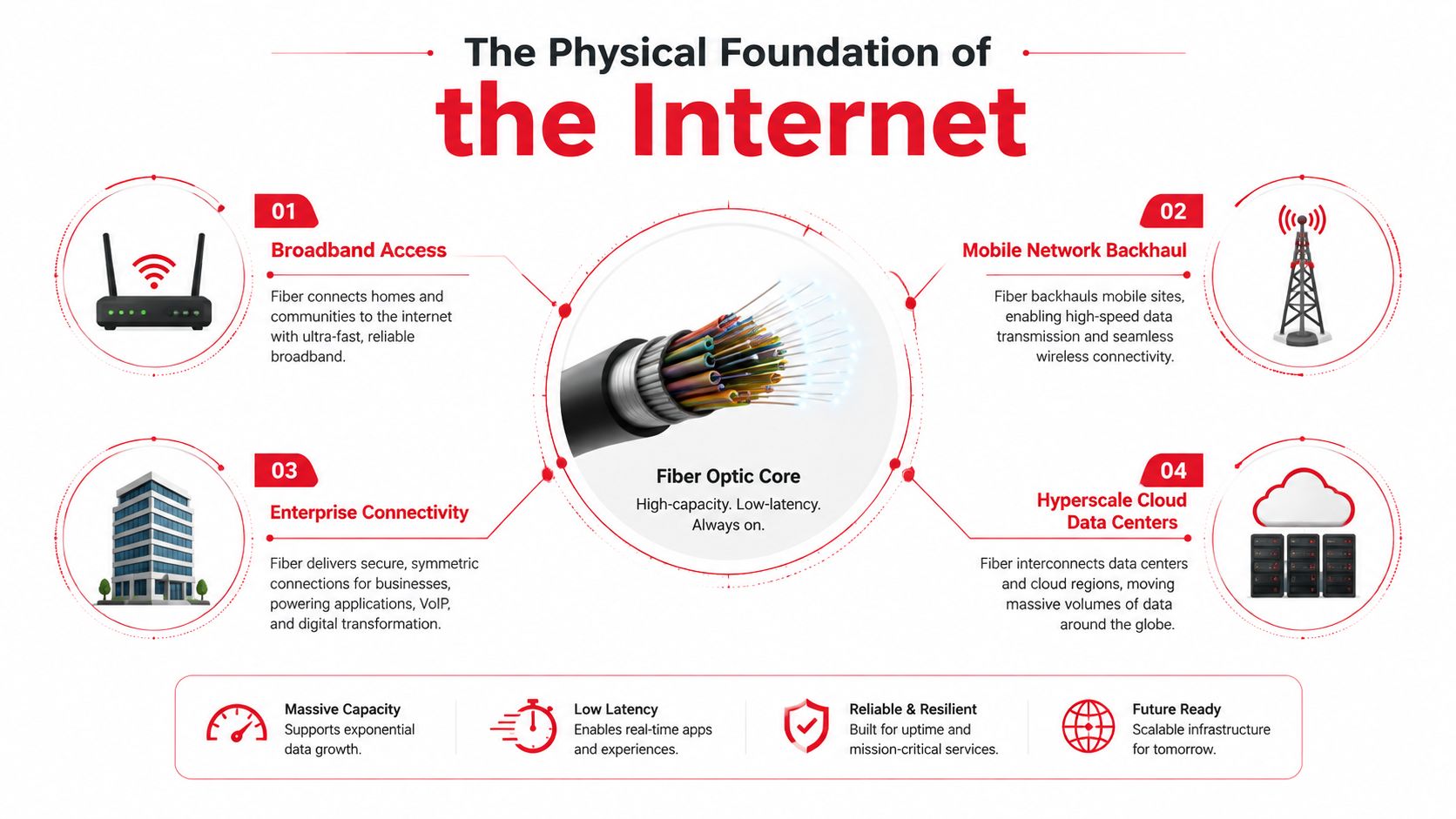
Fiber sits beneath the services people experience as broadband, mobile backhaul, enterprise connectivity, and cloud access. A household router, a cell site, an office circuit, and a hyperscale workload may depend on different service providers, but each connection ultimately relies on physical transport between network points. Industry reporting estimates that fiber carries about 90% of global internet traffic (fiber optic infrastructure statistics).
A practical definition is broader than “fiber cable.” Fiber optic infrastructure is the complete engineered path that moves light between endpoints, including optical cable, conduit, innerduct, handholes, cabinets, splice closures, patch panels, connectors, optical line terminals, transport shelves, power, grounding, and monitoring. The physical plant and the active equipment must work together. A clean cable route with poor connector management can still create service-affecting loss.
Coverage isn't the same as delivered service
Marketing often treats fiber coverage as the finish line. It isn't. A property may be near a fiber route while the final connection still uses copper, or a provider may report a passing without an installed drop, optical terminal, or affordable service plan. BroadbandNow's 2025 state rankings, as summarized by Light Reading, found that several states with fiber coverage above 60% still ranked in the bottom half nationally, while California ranked 18th with 39.7% fiber coverage and Illinois ranked 19th with 33.3% (coverage and broadband affordability analysis).
The useful question is therefore not only, “How many premises can the network reach?” It's also, “What can customers order, at what price, with what measured performance and restoration commitment?” That distinction shapes every design decision covered here, from access architecture to data center interconnects.
For teams mapping the digital layer above this physical plant, an overview of enterprise platform architecture can help connect network dependencies to broader systems planning. The infrastructure lead still has to make the route, cable, splice, and acceptance decisions in the field.
How Fiber Got This Big
Fiber moved from laboratory promise to commercial infrastructure through a sequence of practical breakthroughs. Corning's low-loss fiber work in 1970 made long-distance optical transmission more viable, and AT&T followed with an experimental 2,000-meter fiber link beneath Atlanta that same year. By 1977, non-experimental fiber telecommunications links were being installed in locations including Chicago, according to the historical record compiled by SUNY Polytechnic Institute (history of fiber optics and telecom deployment).
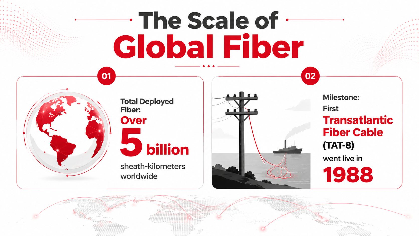
The international proof point arrived in December 1988, when TAT-8 entered service as the first transatlantic fiber-optic cable. That milestone demonstrated that optical transmission could support intercontinental communications at commercial scale, not just controlled laboratory or metropolitan trials.
Capacity grew without rebuilding every route
The important engineering story isn't only the calendar. Single-mode fiber established long-reach transmission as the default for telecom networks, while optical amplifiers and wavelength-division multiplexing allowed operators to increase capacity across existing cable routes. Instead of treating every demand increase as a reason to excavate a new corridor, network owners could add or upgrade optical equipment, subject to the limits of the installed plant.
That legacy changes how planners approach a 2026 project. An old route may still offer valuable duct, rights-of-way, splice locations, and building entrances, but its records may be incomplete and its physical condition may vary. A new extension must fit the existing optical budget, connector standard, restoration process, and maintenance model. The cheapest civil route can become expensive if it creates an awkward splice boundary or forces a carrier to manage incompatible components.
The global footprint is now planetary in scale. One industry summary reports more than 5 billion kilometers of optical fiber deployed worldwide by 2020, while another reports global optical fiber cable production of 210 million kilometers in 2021, up 12% from the prior year (global fiber deployment and production figures). Those figures describe both the accumulated asset and the continuing manufacturing pipeline behind access networks, mobile transport, cloud interconnection, and data center connectivity.
The Four Layers of a Fiber Network
A network becomes easier to design when each layer has a defined job. FTTx solves the access problem, bringing fiber toward homes, businesses, buildings, or other endpoints. A greenfield subdivision might use FTTH, with distribution fiber running through neighborhood routes and drops terminating at each premise. FTTB and FTTO serve building or office environments, while FTTC and FTTN leave part of the access path on a non-fiber medium.
Backbone fiber solves distance and aggregation between cities, countries, submarine cable landings, and major network hubs. Its design prioritizes route diversity, optical reach, amplifier placement, protected facilities, and maintainable splice points. A regional internet exchange connection may use a long intercity span to move traffic between markets, with the optical design driven by distance and capacity rather than by individual subscriber drops.
Metro fiber operates inside a regional market. It often forms rings or diverse paths among central offices, carrier hotels, mobile aggregation sites, enterprise buildings, and data centers. A downtown metro ring may use dense handholes and building entrances, but the network still needs physical separation where a single excavation or utility event could take out both supposedly diverse paths.
Data center interconnect, or DCI, connects colocation facilities, hyperscale campuses, cloud regions, and edge sites. Operators may use dark fiber pairs, leased wavelengths, or optical transport systems. The correct choice depends on ownership, distance, upgrade plans, operational control, and the need to scale interfaces such as 400G and 800G in the relevant equipment environment.
| Layer | Scope | Typical Reach | Primary Use |
|---|---|---|---|
| FTTx | Access edge | Premise or nearby endpoint | Residential, business, and building connectivity |
| Backbone | Intercity, national, or submarine | Long-distance routes | Core transport and major aggregation |
| Metro | Regional market | City or metropolitan area | Carrier, enterprise, mobile, and facility aggregation |
| DCI | Facility to facility | Campus, metro, or regional | Cloud, colocation, storage, and workload transport |
Layer boundaries also affect construction strategy. A modular data center may accelerate facility expansion, but the fiber route still needs coordinated entrances, diverse pathways, splice access, and tested cross-connects. Teams evaluating how modular buildings support rapid growth should treat connectivity as a civil and operational dependency, not an item added after the building arrives.
Inside the Physical Stack
Light starts in a glass core, but the cable assembly protects that core from pulling force, moisture, crushing, abrasion, and bending. A coating surrounds the glass, strength members carry installation loads, and the outer jacket protects the finished cable in its environment. Loose-tube designs isolate fibers inside protective tubes and suit many outside-plant applications. Ribbon cable arranges fibers in a flat structure that can support high-count mass fusion splicing where the route and closure design justify it.
Choose the fiber for the environment
Single-mode OS2 is the normal choice for outside plant, access, metro, backbone, and most DCI applications because it supports long distances and optical upgrades. Multimode, including OM3, OM4, and OM5, earns its place in shorter premise and data center links where the optical interfaces, reach requirements, and installed structured cabling standard support it. Mixing these categories casually creates a procurement and operations problem. The design has to match transceivers, patching, polarity, testing, and future expansion.
The pathway deserves the same attention. Conduit sizing must allow installation tension, bend control, future capacity, and maintenance access. Innerduct can separate cables, protect a new subnetwork, and make later pulls more manageable. A 1.25-inch HDPE run may carry multiple sub-ducts when the route design supports that arrangement, but the team still has to verify fill, pulling tension, bend geometry, and access points before construction.
Splicing and connector discipline
Fusion splicing generally provides a low-loss permanent joint for outside plant and backbone routes. Pre-terminated MPO or MTP assemblies can reduce field termination work in controlled data center environments, but they demand disciplined polarity, cassette, trunk, and connector inspection practices. UPC and APC polish types aren't interchangeable design details. APC interfaces require compatible mating components and are commonly selected where return-loss performance is important.
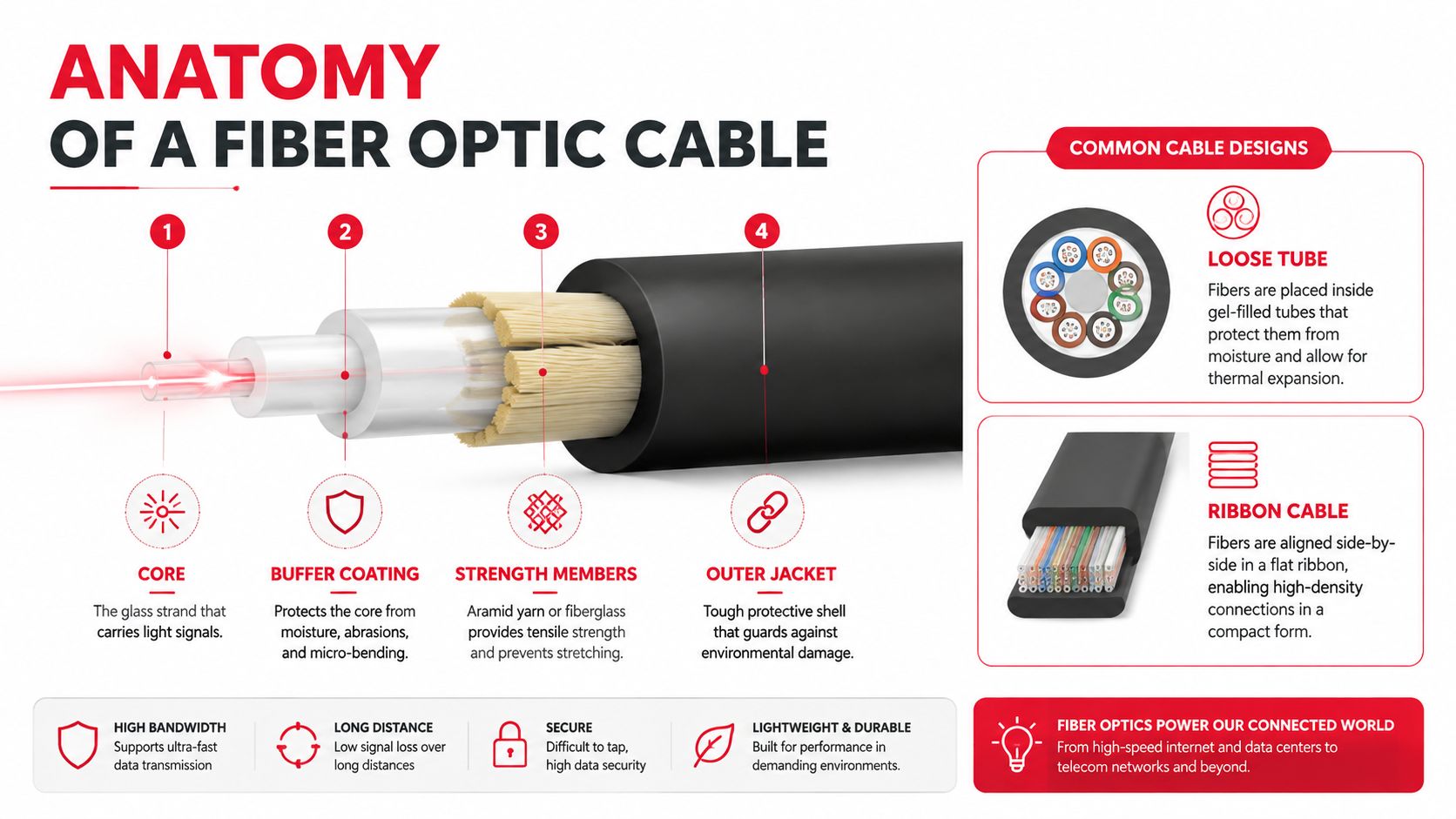
Bend management is a hard engineering constraint. Industry guidance commonly uses a minimum bend radius of about 20 times the cable's outer diameter during installation and 10 times the diameter after placement, because tighter bends can increase macrobending loss and attenuation. Bend-insensitive G.657 variants help where routing space is constrained, but they don't excuse poor handling (fiber cable installation and bend-radius guidance).
The final physical layer includes patch panels, optical distribution frames, splice trays, slack loops, cabinet organizers, and meet-me-room cross-connects. Slack must be accessible without disturbing live circuits. Every bend, splice, connector, and label is a design decision made before the reel reaches the site.
A field demonstration of the cable path and handling principles is available below.
Aerial, Underground, and Directional Boring Compared
No single construction method wins every route. Aerial plant can be economical and quick where suitable poles, attachment rights, clearances, and make-ready capacity already exist. It remains exposed to storms, vehicle strikes, vegetation, pole damage, and shared-pole outages.
Underground construction provides more physical protection after restoration, but the work encounters existing utilities, pavement, drainage, private entrances, and restoration requirements. Direct burial or plowing can work well in open corridors, while trenching becomes disruptive in dense streets. Horizontal directional drilling, or HDD, costs more in many situations, but it can cross driveways, roads, waterways, and sensitive surfaces without opening the full corridor.
Current industry benchmarks put typical underground builds at about $18 per foot and aerial builds at about $8 per foot. The same benchmark attributes roughly 72% of underground cost and 64% of aerial cost to labor, which explains why construction method, permitting, crew productivity, and make-ready often matter more than the fiber itself (fiber deployment cost benchmark).
| Method | Typical Per-Mile Cost | Deployment Speed | Surface Disruption | Long-Term Risk |
|---|---|---|---|---|
| Aerial | Lower where existing poles are usable | Fast after make-ready | Limited surface work | Storm, clearance, and pole damage exposure |
| Underground | Higher civil cost | Varies with utility conflicts | Trenching and restoration required | Better physical protection, but vulnerable to third-party excavation |
| HDD | Higher specialized construction cost | Efficient across obstacles, slower to mobilize | Low at the surface | Bore accuracy, subsurface conditions, and duct integrity matter |
A suburban FTTH lateral often combines all three. The main route may lash aerial fiber along a rear easement, HDD may pass beneath a driveway, and a handhole at the property line may provide the transition to the drop. That mixed approach usually beats forcing one method across every parcel because it assigns each segment to the method that best fits its access, disruption, and risk profile.
Field rule: Standardize the design criteria, not necessarily the construction method. A route that looks uniform on a map rarely behaves uniformly in the ground or on the poles.
From Design and Permitting to Make-Ready
Schedules are usually won before the first crew arrives. High-level routing starts with GIS, road rights-of-way, utility records, existing ducts, building entrances, and known network assets. The route then becomes a low-level design with handholes, pole spans, cable sizes, slack locations, splice points, crossing details, restoration notes, and a bill of materials.
Build the pre-construction sequence
- Route the corridor: Identify feasible paths and obvious constraints before detailed drafting. Confirm that the route connects real access points, not just map coordinates.
- Secure permissions: Coordinate municipal right-of-way permits, pole attachment orders, railroad easements, environmental reviews, archaeological requirements, and private property access. The governing jurisdiction often sets the critical path.
- Complete the low-level design: Verify span calculations, attachment locations, conduit paths, vault spacing, splice architecture, and serviceability. A design that cannot be staked clearly isn't ready for construction.
- Coordinate make-ready: Survey the poles, obtain pole-owner engineering, identify required rearrangements, allocate qualified contractors, and track approvals. Aerial make-ready can add months when multiple owners or utilities must act in sequence.
- Lock the build package: Complete constructability review, freeze the BOM, confirm material availability, assign crews, establish traffic-control plans, and define acceptance criteria.
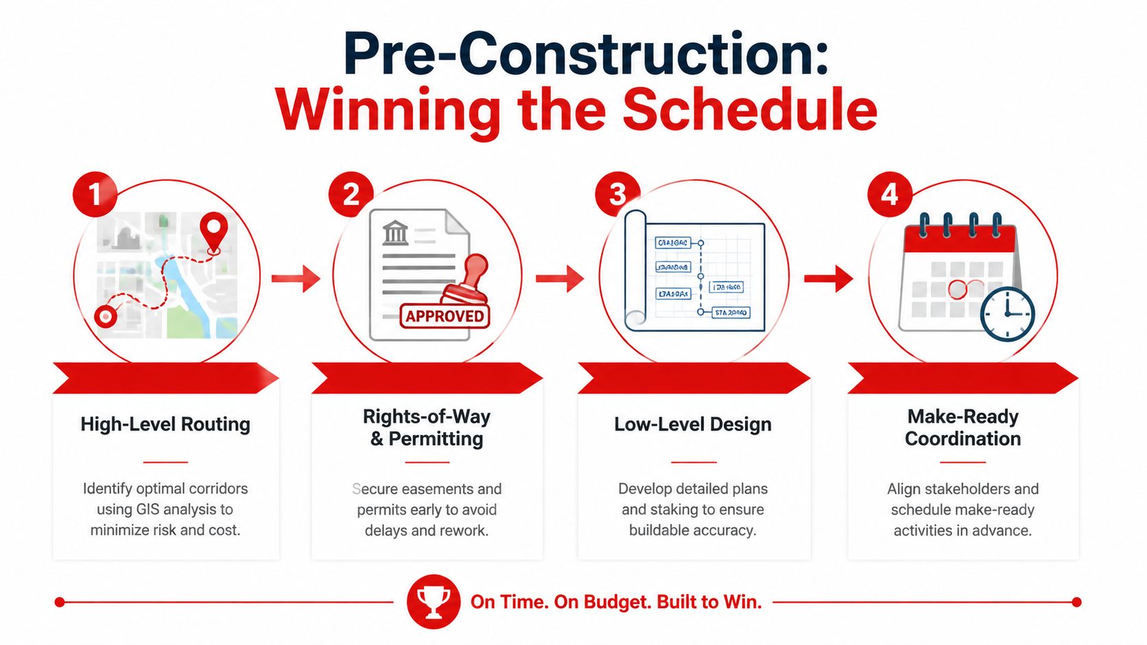
Permitting isn't administrative overhead that can be cleaned up later. A missing railroad approval or unresolved utility conflict can strand materials and crews while the project burns schedule. The same applies to make-ready. If the design assumes a pole is available but the pole owner requires rearrangement, the route isn't construction-ready.
Recent industry reporting shows why this pre-work deserves financial attention. The Fiber Broadband Association reported that 92% of respondents saw deployment cost increases in 2025, and 88% expected further increases in 2026, citing labor, materials, permitting, and make-ready pressure (fiber broadband deployment cost and build-rate report). A good pre-construction process doesn't remove those pressures, but it prevents avoidable surprises from becoming field change orders.
Testing, Documentation, and Long-Term Maintenance
A fiber plant becomes an operational asset only after the owner can prove what was installed and how it performed. Acceptance should progress from basic verification to characterization. Tier 1 checks continuity, polarity, power levels, and obvious link faults. Tier 2 uses OTDR traces, ideally from both directions, with reference splices and launch and receive considerations that make the results interpretable. Tier 3 evaluates dispersion and wavelength behavior where the route, service, or optical design requires it.
The test result has to connect to the service obligation. If a circuit has an optical loss limit or restoration requirement, the owner needs fiber-specific evidence, not a generic statement that “testing passed.” Trace files, power readings, splice records, connector inspection results, and exception approvals should be tied to the same fiber ID used in the splice schedule and GIS.
Demand an as-built package that works in operations
A useful closeout package includes:
- GIS-aligned route records: Show the installed path, structure IDs, handholes, cabinets, entrances, and span relationships.
- Fiber-level splice documentation: Identify every splice, tray position, closure, and endpoint.
- Measured test evidence: Key OTDR traces, insertion-loss results, power checks, and any required characterization to the fiber ID.
- Physical design records: Include cable type, sheath length, slack placement, conduit or innerduct assignment, and connector details.
- Exception history: Record deviations, approved field changes, damaged fibers, repairs, and unresolved conditions.
Poor documentation creates operational debt. A technician who can't identify the correct tray or route may disturb live services during restoration. An unlabeled spare can become unusable capacity. A map that shows planned infrastructure instead of installed infrastructure sends crews to the wrong handhole.
Maintenance also needs a field model. Water ingress at handholes, rodent damage to aerial drops, crushed conduit, contaminated connectors, and damaged closures all require different responses. Scheduled inspection, cleaning procedures, spare materials, emergency contacts, and restoration windows protect the plant over its service life. The goal isn't to eliminate every failure. It's to make failures diagnosable, repairable, and properly recorded.
Choosing a Turnkey Fiber Infrastructure Partner
A low bid can conceal the costs that appear after construction. Missing as-builts, undocumented splices, incomplete make-ready, weak connector inspection, and rushed acceptance may leave an owner with a network that passes coverage checks but performs poorly in service. The broader market already shows why coverage alone isn't enough. Fiber availability can coexist with weak broadband outcomes when affordability, adoption, competition, or service quality remain unresolved, as documented in the earlier coverage analysis.
The partner must therefore be evaluated as an operating system for the project, not merely as a labor source. Ask who owns the design, who secures permits, who performs the splice work, who controls the testing records, and who remains available when a route fails after turnover.
RFP questions that expose delivery risk
- Engineering ownership: Does the partner perform route design, span calculations, splice design, and constructability review in-house?
- Field capability: Are splicing, termination, testing, boring, and restoration crews self-performed or subcontracted?
- Permitting control: Who tracks permit conditions, utility coordination, railroad access, and pole-owner approvals?
- Testing discipline: Are field technicians trained and certified for the OTDR and power-meter procedures specified in the acceptance plan?
- Documentation quality: Will the owner receive GIS-aligned as-builts, fiber-level splice schedules, labeled traces, and approved deviation records?
- Schedule accountability: What escalation path applies to missed milestones, and will the partner accept meaningful schedule consequences where appropriate?
- Restoration readiness: What fleet, inventory, staffing, and response process support emergency repair?
| Capability | Must-Have | Nice-to-Have | Red Flag |
|---|---|---|---|
| Engineering | Signed low-level design and constructability review | Integrated GIS and field staking workflow | Design handed off without field validation |
| Construction | Qualified aerial, underground, and HDD capacity | Flexible mixed-method deployment | One method forced across every route |
| Splicing and testing | Documented fusion, inspection, OTDR, and acceptance process | Centralized trace management | “Pass” reports without fiber-level evidence |
| Permitting | Named owners and permit tracker | Established utility and agency relationships | Permit responsibility left unclear |
| Closeout | Complete as-builts tied to installed assets | Digital handover integrated with operations | Redlines delivered late or incomplete |
| Maintenance | Restoration plan, spares, and escalation contacts | 24/7 mobilization capability | No post-construction support model |
Southern Tier Resources offers an end-to-end option for this lifecycle, including fiber design, construction, make-ready coordination, splicing, testing, documentation, maintenance, and data center infrastructure fit-outs. Its scope also includes wireless infrastructure work, which can matter when fiber transport and mobile site deployment share a program.
The selection decision should rest on evidence. Review sample test packages, inspect a completed splice closure, verify insurance and licenses, ask for references from comparable route environments, and require the proposed project manager to explain how exceptions will be recorded. The partner that communicates bad news early is usually safer than the bidder that promises an effortless build.
Southern Tier Resources can help carriers, ISPs, data center operators, and enterprise teams plan and deliver fiber optic infrastructure from routing and permitting through construction, splicing, testing, and maintenance. Visit Southern Tier Resources to discuss a turnkey build or fit-out with a team equipped to manage the physical network lifecycle.