You're at the closure, the splice tray is nearly dressed, and the fusion splicer reports a clean-looking joint. Then the OTDR shows 0.42 dB at one splice. That single reading can consume more margin than the splice itself appears to deserve, especially when the route already includes connectors, fiber attenuation, bends, and engineering allowance.
That's why experienced crews don't judge fiber splicing loss as an isolated event. They treat every joint as a debit against the optical budget. A low reading protects the route. A mediocre reading may pass on its own yet become a problem when repeated across a backbone, access route, or data-center plant.
What Fiber Splicing Loss Actually Means in the Field
Fiber splicing loss is the reduction in optical power at the point where two fibers are joined, expressed in decibels. The joint may be made by fusion splicing, which permanently melts the glass together, or by mechanical splicing, which aligns the fibers inside a sleeve or precision holder. Neither method creates a completely lossless transition.
A splice reading becomes meaningful only in relation to the whole link. The FOA explanation of optical loss estimation illustrates the budgeting problem with a route containing 40 splices. At a planned 0.15 dB per splice, those joints consume about 6 dB before connectors, fiber attenuation, and engineering margin are included. That's not a defect in one joint. It's a route-level allocation.
Separate fiber mismatch from workmanship
Some loss is intrinsic to the fibers being joined. Mode-field diameter, core geometry, numerical aperture, and refractive-index profile can differ between fiber types, so the splice may retain a loss component even when the technician prepares and aligns both ends correctly. A transition between unlike fibers should never be judged by the same expectation as two closely matched lengths of standard single-mode fiber.
Extrinsic loss comes from the work itself. Lateral core offset, angular error, a poor cleave, contamination, an axial gap, or an unstable fusion arc can all increase attenuation at the joint. These are the problems a technician can usually correct through preparation, equipment maintenance, or a resplice.
Practical rule: A splice estimate tells you whether the joint looks healthy. The link budget tells you whether the route can tolerate the joint.
The numbers are small because decibels are logarithmic, but the operational effect accumulates. Industry field guidance commonly treats 0.3 dB per splice as a widely used planning ceiling, while best-practice fusion work is often targeted around 0.05 to 0.08 dB average. The difference is roughly a 7% linear power reduction at 0.3 dB, compared with about 1% at 0.05 dB, as described in this field guidance on OTDR testing and splice-loss acceptance.
That framing changes the question at the closure. Instead of asking only, “Is this splice acceptable?”, ask, “How much of the route's remaining margin does this splice consume, and can the next technician prove where that loss came from?”
The Main Causes of Fiber Splicing Loss
High fiber splicing loss usually comes from a short list of physical conditions. The useful field skill is matching the reading and trace shape to the likely cause before opening the closure.
| Cause | Typical dB Impact | Field Signal |
|---|---|---|
| Core misalignment | Can add 0.1 to 0.3 dB for a lateral offset of 1 micron, with angular misalignment above 1 degree capable of pushing loss beyond 0.5 dB | A sharp, nonreflective step or a large estimated loss after alignment |
| Poor cleave angle | A 1.5-degree cleave can add tenths of a decibel | Uneven fiber ends, repeated high estimates, or a visibly chipped face |
| Contamination | Can add tenths of a decibel independently | Unstable readings, dirty V-grooves, or a splice that improves after cleaning |
| Refractive-index or fiber-geometry mismatch | Inherent loss that technique cannot fully remove | Direction-dependent OTDR values, gainers, or persistent loss after careful resplicing |
The quantitative examples in the table are drawn from the supplied field guidance on common causes of splice loss. Use them as diagnostic clues, not as guaranteed outcomes for every fiber, splicer, or test setup.
Alignment errors are often the first suspect
A fusion splicer can align claddings while the cores remain offset. Core-alignment equipment reduces that risk by using imaging and controlled movement to position the cores rather than relying only on the outside glass diameter. If the machine repeatedly reports high estimates on otherwise clean fiber, verify the alignment mode, fiber recipe, calibration state, and V-groove condition.
Angular misalignment points to cleave quality or fiber seating. The two fiber ends may touch while their axes do not form a smooth optical path. A joint like that can show higher loss, a reflection, or both.
The cleaver has more influence than the display suggests
A fusion splicer can estimate loss, but it can't turn a chipped or angled end face into a square one. Inspect the cleave, confirm that the fiber is seated correctly, and reject questionable ends before the arc starts. Contamination behaves similarly. A small particle on the end face or in the V-groove changes the gap and the arc interaction, so cleaning the fiber alone isn't enough if the holder remains dirty.
Fiber mismatch requires a different response. A G.652-to-G.655 transition, or a multimode transition between different core sizes, may retain loss after excellent preparation. The technician should document the fiber types and avoid treating an unavoidable transition loss as a workmanship failure.
Acceptable Splice Loss Thresholds and Industry Benchmarks
Project specifications govern acceptance, but crews still need consistent working values. For link-budget planning, 0.3 dB per splice remains a widely used acceptance ceiling for fusion and mechanical splices. Field guidance places best-practice fusion results around 0.05 to 0.08 dB average, so a ceiling should be treated as a limit, not a production target. The TIA-aligned splice-loss benchmark discussion explains that distinction.
The FOA lists 0.15 dB per single-mode fusion splice as a commonly cited planning value. Design calculations often use 0.3 dB per multimode mechanical splice. The FOA optical loss estimation guidance also makes the field consequence clear: every splice consumes part of the route's available loss budget. A single acceptable event can become a route problem when several joints run high.
Read the standard in context
Older guidance helps explain why current workmanship expectations are tighter than some mechanical-splice allowances. ITU-T Recommendation L.12, issued in May 2000, recommended average losses of no more than 0.1 dB for single-fusion splices in trunking routes and no more than 0.2 dB in access networks. It also described maximum values reaching 0.5 dB for 95% of cases in some categories and permitted mechanical-splice losses up to 0.8 dB in certain access-network applications.
| Standard / Source | Per-Splice Target | Acceptance Ceiling | Notes |
|---|---|---|---|
| TIA-aligned field benchmark | 0.05 to 0.08 dB for best-practice fusion work | 0.3 dB | The target is materially lower than the planning ceiling |
| FOA planning guidance | 0.15 dB for single-mode fusion | Route-specific | Use the value within the complete link budget |
| ITU-T L.12 historical guidance | 0.1 dB trunking average, 0.2 dB access average | Category-dependent values up to 0.5 dB | Older guidance also allowed higher mechanical-splice values |
| Project specification | Defined by the contract | Defined by the contract | The approved design and acceptance plan govern final sign-off |
For a project manager, a 0.25 dB result requires a qualified answer. Review test uncertainty, splice history, route budget, fiber type, and the project threshold before approving it. One reading may pass the stated limit, while repeated results at that level can steadily reduce the margin available across the completed route. Record the result with its test conditions, then decide whether the pattern warrants corrective work.
Measuring Splice Loss with OTDR and Power Meters
A splice can look clean on the machine and still consume more of the link budget after routing, bending, and closure work. That is why crews use two different tests. An OTDR locates and characterizes individual events, while a light source and power meter, commonly called OLTS, measures total end-to-end optical loss and provides the stronger basis for final link certification.
An OTDR sends pulses through the fiber and interprets returned backscatter. It helps locate events, compare a new trace with an earlier trace, and identify the splice that deserves inspection. The reading depends on test direction because the two fibers can have different backscatter characteristics. A transition between unlike fibers can also appear as either a loss or a gain.
Use the OTDR as a locator and diagnostic instrument
Use suitable launch and receive fibers when checking events near either end of the link. Set the wavelength, pulse width, range, averaging, and event thresholds consistently across the test set. If the project requires splice-level verification, test from both directions and treat the result as a bidirectional assessment. One directional number can misrepresent the actual splice condition.
Per guidance on OTDR and source-meter splice testing, a fusion-splicer estimate does not account for every bend, tray-routing condition, or installation effect introduced after the splice leaves the machine. Use that estimate for process control, then verify the installed fiber with field instruments.
| Attribute | OTDR | Power Meter + Light Source (OLTS) |
|---|---|---|
| Primary purpose | Locate and characterize events | Measure total end-to-end insertion loss |
| Splice isolation | Strong, especially with a clear trace | Not practical for isolating one installed splice |
| Directional sensitivity | Yes, especially across unlike fiber | Uses a direct source-to-meter measurement |
| Launch and receive fibers | Important for end events and event resolution | Required according to the applicable test method |
| Best field use | Troubleshooting and event mapping | Final acceptance and warranty records |
| Main limitation | Interpretation can be affected by backscatter and direction | It cannot identify which individual splice caused total loss |
A power-meter test requires a stable light source and a consistent reference procedure. Do not use OLTS to guess which splice is bad, and do not treat one OTDR direction as proof that every joint meets the contract. The practical sequence is straightforward: use the OTDR to find the event, then use the appropriate reference test to validate the link or confirm the repair.
Record wavelength, direction, launch and receive setup, trace settings, and the final end-to-end result. Those details show whether a rising loss pattern comes from one splice or from several small losses consuming the same route budget.
Troubleshooting High Splice Loss Step by Step
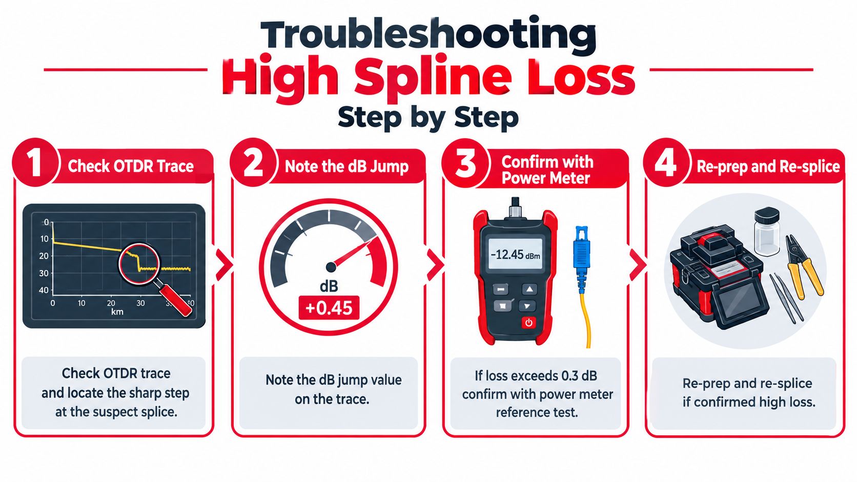
Start with the trace, not the splice tray. Locate the event number, record the measured step, note the test direction and wavelength, and compare it with the opposite-direction trace when available. If the event exceeds the project threshold or the widely used 0.3 dB ceiling, confirm the concern with a suitable power-meter reference test before disturbing a sealed closure.
Follow the physical evidence
Open the closure only after recording the original evidence. Match the splice number to the tray position, inspect the joint and sleeve, check for tension or a sharp bend, and examine the fiber ends and V-grooves under magnification. Look for contamination, a chipped cleave, an axial gap, an uneven fusion profile, or damage introduced while routing the fiber into the tray.
Clean with approved lint-free wipes and cleaning fluid, but don't assume cleaning alone will fix a bad end face. If contamination or cleave damage remains possible, strip back as required, recleave the fiber, and resplice using the correct fiber program and arc settings.
Trace clue: A reflective spike points toward an air gap, poor fusion, or another discontinuity. A gainer can indicate a backscatter mismatch rather than actual optical power gain. Ghost events may be reflections or processing artifacts that need confirmation with settings and direction changes.
After the repair, repeat the same test setup used for the original trace. Compare event location, loss, reflectance, and the full route shape. Save both traces, record what changed, and don't close the work order until the new result is tied to the physical splice location.
Best Practices That Prevent Splice Loss Before It Happens
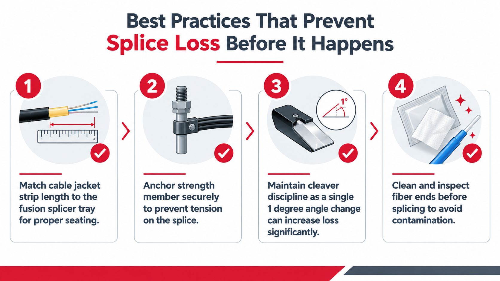
Low-loss work begins before the fibers enter the fusion splicer. Match the jacket strip length to the splice tray and secure the strength member so cable tension doesn't transfer into the finished joint. A splice that looks perfect on the machine can develop routing stress if the tray geometry and anchoring are wrong.
Prepare the work area and machine
Use a tent or enclosure when wind, dust, or temperature changes threaten arc stability. Clean the splicer body, V-grooves, holders, electrodes, and cleaver according to the equipment manufacturer's maintenance procedure. Run the machine's arc test and calibration routine for the fiber type and current conditions, then replace worn electrodes according to the manufacturer's service guidance rather than waiting for repeated failures.
Cleaver discipline separates repeatable work from callback work. Keep the blade clean, rotate or index it according to its service procedure, and handle freshly cleaved fiber by the coating rather than touching the glass. A 1-degree change in cleave angle can add 0.1 dB, according to the supplied field guidance, so a technician should inspect the cleave rather than trusting the cleaver to produce an acceptable end every time.
Before pressing splice, check four things:
- Tray fit: The stripped cable should seat naturally without forcing the fibers into an unnatural bend.
- Strength-member anchor: The closure and tray must carry cable tension, not the glass at the splice.
- Cleave inspection: Reject angled, chipped, dirty, or visibly damaged fiber ends.
- Arc verification: Confirm the fiber recipe and run the appropriate calibration or arc test after environmental conditions change.
Don't chase an estimated loss number by repeatedly pressing “splice” on contaminated or poorly cleaved fiber. Repeated arcs won't repair preparation errors. The reliable sequence is clean, inspect, recleave when necessary, calibrate, splice, protect, and then test under the project's acceptance procedure.
Documenting Splice Performance for As-Built Records
A test result has limited value if another crew can't find the physical joint it describes. Per-splice documentation should connect the loss reading, splice number, tray position, closure, fiber identity, and technician in one record.
Capture the fusion splicer's estimated loss, the OTDR result in both directions at 1310 nm and 1550 nm, the trace screenshot, closure location, fiber and buffer-tube colors, and technician initials. The wavelength values and documentation fields should follow the project test plan and client template. Add the cleaver service record and fusion-machine calibration entry so a later reviewer can distinguish a fiber problem from equipment condition.
Build records for the next technician
Use a consistent naming convention for traces and photos. A PDF splice map, GIS update, or cloud fiber-management platform can all work if the identifiers remain consistent across the splice sheet, closure label, OTDR files, and final handoff package.
A practical record package includes:
- Splice identity: Closure, tray, splice number, fiber number, tube color, and route segment.
- Test evidence: OTDR traces, direction, wavelength, settings, and measured event loss.
- Physical evidence: Closure-label photo, tray position, sleeve placement, and slack-loop condition.
- Quality history: Estimated splice loss, cleaver condition, calibration entry, and any resplice.
- Exception handling: A red flag for any value over the project threshold, followed by a resplice or documented engineering variance.
Southern Tier Resources describes its fiber work as including splicing, testing, and detailed as-built documentation for wireline deployments. That kind of integrated handoff matters because future maintenance depends on records that connect test data to the plant in the field.
Putting Splice Loss in Perspective for Long-Term Network Health
Treat splice loss like interest charged against the link budget. A route can survive one slightly high joint, but repeated overruns reduce the margin available for connector contamination, aging, bends, repairs, and future network changes. The route may pass today while leaving less tolerance for tomorrow's maintenance.
A simple planning example shows the compounding effect. If 0.2 dB of avoidable overrun appears at 20 joints, the route carries 4 dB less margin than the design assumed. That calculation uses the supplied verified data and illustrates why crews should manage the route total rather than celebrate isolated pass readings.
Make the budget visible in daily work
A disciplined crew protects future capacity through ordinary habits:
- Calibrate before production splicing.
- Inspect the cleaver and fiber ends before every joint.
- Use two-direction OTDR verification when splice-level accuracy matters.
- Confirm final link loss with the prescribed source-and-meter method.
- Save traces and photos under a naming system another crew can decode.
- Escalate repeated borderline readings instead of normalizing them.
Specialty fibers require extra caution. A 2026 peer-reviewed study on few-mode fiber found that conventional backscattering-based splice-loss measurement deviated by as much as 2.45 dB, while model predictions remained within 0.24 dB, as reported in the PubMed record for the study. The same verified source also describes 2026 industry reporting on hollow-core routes, including Microsoft Azure deployed-route data with mean splice loss of 0.16 dB and individual splices as low as 0.04 dB. Those results reinforce a practical rule: when the fiber changes, validate the measurement method before applying standard single-mode heuristics.
Small dB values repeated across a plant decide whether the network has room for repairs and upgrades. Crews that measure carefully, correct preparation faults early, and document every joint leave operators with a link that can be maintained without guesswork.
Southern Tier Resources provides fiber construction, fusion splicing, testing, and as-built documentation for telecom, broadband, and data-center infrastructure. If your next deployment needs accountable field execution and splice records that support long-term maintenance, visit Southern Tier Resources to discuss the project.