
When you're joining two fiber optic cables, the goal is to create a seamless connection that allows light to pass through with almost no disruption. This involves precisely preparing and aligning two fiber ends before permanently joining them. It’s a meticulous process, but one that’s absolutely critical for network reliability.
Why a Perfect Fiber Splice Matters
Before you even think about stripping a cable, it's crucial to grasp what separates a professional splice from a shoddy one. Getting this right isn't just about connecting two lines; it’s about creating an optical path so perfect that the signal barely knows it passed through a join.
Even a microscopic flaw—a fleck of dust, a tiny air gap, or a slightly off-angle cleave—can wreak havoc on the light signal. These imperfections lead to high insertion loss, where the signal weakens, and back reflection, where the signal bounces back toward its source. The result? Degraded network performance, sluggish data speeds, and frustrated end-users.
The Two Go-To Splicing Methods
Out in the field, technicians have two primary methods in their toolkit. Each has its place, and knowing when to use which is the first mark of an experienced pro.
-
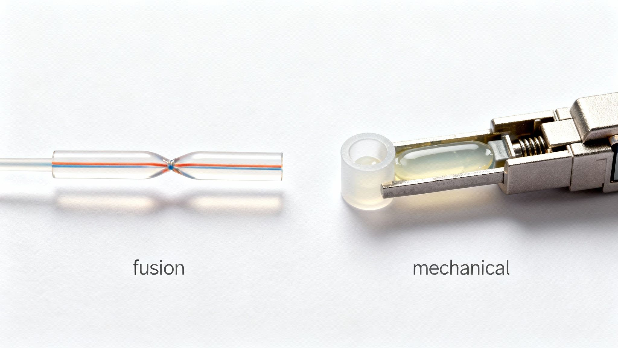
Fusion Splicing: This is the gold standard for permanent, high-performance connections. A fusion splicer uses a controlled electric arc to literally melt the two glass fiber ends and weld them into a single, continuous strand. Nothing beats it for creating a strong, low-loss bond.
-
Mechanical Splicing: This method is a bit different. It uses a small, self-contained device that precisely aligns the fibers and clamps them together. An index-matching gel inside the splice housing fills the minuscule gap between the ends, helping the light pass through with less reflection. It's much faster and the equipment is less expensive, making it a great option for emergency repairs or less demanding network segments.
The core principle is simple: light travels best through a uniform medium. A fusion splice essentially recreates that uniformity by welding the glass, while a mechanical splice uses a gel to trick the light into seeing a continuous path.
Fusion vs. Mechanical Splicing At a Glance
To make the choice clearer, here’s a direct comparison of the two methods. Understanding these trade-offs will help you decide which approach is right for your specific situation.
| Attribute | Fusion Splicing | Mechanical Splicing |
|---|---|---|
| Performance | Excellent, very low signal loss (0.01–0.1 dB). | Good, but higher loss than fusion (0.2–0.75 dB). |
| Durability | Extremely high; a permanent, welded bond. | Good, but susceptible to temperature changes & vibration. |
| Upfront Cost | High (fusion splicer machines are expensive). | Low (requires only basic hand tools). |
| Cost Per Splice | Low (splice protection sleeves are inexpensive). | High (each mechanical splice is a consumable part). |
| Best For | Long-haul networks, data centers, permanent installs. | Emergency repairs, temporary connections, FTTx drops. |
| Speed & Skill | Requires more training and is slower per splice. | Very fast, requires minimal training. |
While mechanical splices have their place, the industry has clearly favored fusion for any critical infrastructure.
The Industry Shift to Fusion
Professionals started moving away from mechanical splices and toward fusion back in the late 1980s. By the 2000s, it wasn't even a debate—fusion splicing had become the standard. The reason is performance. With typical insertion losses of just 0.01–0.1 dB, fusion splicing is worlds better than the higher, less predictable losses from mechanical splices.
This technical superiority has created a huge demand. The global fusion splicer market hit around USD 830.0 million in 2024 and is expected to keep growing as providers race to build out fiber networks for broadband and 5G.
Ultimately, choosing the right method comes down to the job at hand. Are you doing a quick field repair or building out core network infrastructure? This foundational knowledge is key to every step that follows and is central to delivering professional broadband and telecom services.
Gearing Up: Assembling Your Professional Splicing Toolkit
Walking onto a job site unprepared is a recipe for disaster. I've seen it happen. A clean, low-loss splice is simply impossible without the right equipment, and knowing what to have in your bag separates the seasoned pros from the novices. Your toolkit isn't just a random assortment of gear; it’s a complete system built for precision and efficiency.
While the splicer itself—whether fusion or mechanical—is the heart of the operation, the real make-or-break tools are the ones you use for preparation. Trying to save a few bucks on prep tools will almost always cost you more in the long run through wasted time, failed tests, and frustrating callbacks.
The Unsung Hero of Your Toolbag
Believe it or not, your high-precision fiber cleaver is probably the most critical tool you'll own. Its one and only job is to create a perfectly flat, 90-degree end face on the fiber. A cheap or poorly maintained cleaver will give you angled, chipped, or flawed ends every time. No fusion splicer on earth, no matter how advanced, can compensate for a bad cleave.
Investing in a quality cleaver, preferably one with a rotating blade and a built-in scrap collector, isn't just a good idea—it's essential for professional work.
Just as critical are your fiber strippers. You'll need a specific tool for each layer to avoid damaging the delicate glass core.
- Jacket Strippers: These handle the tough outer cable jacket.
- Buffer Tube Strippers: Designed to safely score and remove the buffer tubes protecting the fiber bundles.
- Fiber Strippers: These are the most precise, with specifically milled holes for the 250-micron coating and the 900-micron tight buffer, finally exposing the 125-micron cladding.
Using the wrong stripper or a dull, damaged one is a surefire way to nick the fiber, creating a weak point that’s guaranteed to break later.
Here's a look at a modern fusion splicer, which handles the delicate work of aligning and welding the fibers with incredible precision.
You can see the V-grooves that hold the fibers perfectly in place and the screen for inspecting the alignment—a testament to the microscopic precision this job demands.
To get the job done right, you need a well-organized and fully stocked toolkit. Here’s a detailed checklist of what every professional technician should carry.
Essential Fiber Optic Splicing Toolkit Checklist
| Tool/Material Category | Specific Item | Primary Function |
|---|---|---|
| Splicing & Cleaving | Fusion Splicer | Aligns and fuses two fiber ends together with an electric arc. |
| High-Precision Cleaver | Creates a perfectly flat, 90-degree end face on the fiber. | |
| Fiber Preparation | Jacket Stripper | Removes the outer cable jacket (e.g., PE, PVC). |
| Buffer Tube Stripper | Scores and removes buffer tubes without damaging fibers. | |
| Fiber Stripper (3-hole) | Removes 900μm buffer, 250μm coating, and exposes 125μm cladding. | |
| Cleaning Supplies | 99% Isopropyl Alcohol (IPA) | Dissolves contaminants, oils, and buffer gel from fiber. |
| Lint-Free Wipes | Cleans bare fiber with IPA without leaving residue. | |
| Canned Air / Dust Blower | Removes dust from V-grooves and work surfaces. | |
| Consumables | Splice Protection Sleeves | Protects the finished splice and provides mechanical strength. |
| Fiber Optic Cleaning Swabs | Cleans splicer V-grooves, lenses, and connector end faces. | |
| Inspection & Testing | Visual Fault Locator (VFL) | Identifies breaks or bends in a fiber with a visible red laser. |
| Power Meter & Light Source | Measures signal loss (attenuation) across the splice. | |
| Hand Tools & Safety | Fiber Optic Scissors/Shears | Cuts through Kevlar strength members. |
| Safety Glasses | Protects eyes from glass shards and chemical splashes. | |
| Fiber Scrap Trash Can | Safely disposes of sharp fiber scraps. |
Having these items on hand and in good working order is non-negotiable for professional results.
Don't Overlook Your Consumables
A pristine splice demands a surgically clean workspace. The smallest speck of dust or oil from your skin can block the light path, causing significant signal loss or reflections. Your cleaning supplies are just as important as your splicer.
Cleanliness isn't just a suggestion; it's a non-negotiable rule. Contamination is the number one enemy of a good splice. Every fiber must be spotless before it's cleaved and again before it's spliced.
Make sure your consumable kit is always stocked with these essentials:
- 99% Isopropyl Alcohol (IPA): The industry standard for a reason. It's the best solvent for cutting through the gel, oils, and dirt found on bare fiber.
- Lint-Free Wipes: Never use a regular cloth or paper towel. These special wipes are designed to clean the fiber without leaving any threads or residue behind.
- Splice Protection Sleeves: These little tubes are your splice's armor. You slide one onto the fiber before splicing, then heat it afterward to shrink it down, sealing the connection and giving it the strength it needs to survive in the field.
Putting together a solid toolkit comes with time and field experience. If you want to dig deeper into the tools of the trade, you can find more professional insights on fiber optics and best practices. Remember, every single item in your kit has a critical role to play in achieving that perfect, near-zero-loss connection.
Getting Hands-On: The Step-by-Step Splicing Workflow
Alright, we've covered the theory and the tools. Now it's time to get down to the actual hands-on work of making a perfect splice. This is where a steady hand and a meticulous process make all the difference. We’ll walk through the entire sequence, from breaking into the cable to securing the finished connection, focusing on the professional habits that lead to a solid, low-loss splice every single time.
First things first, you have to get to the fibers. This means carefully stripping the main cable jacket and any armor without ever touching the buffer tubes inside. Once the tubes are exposed, you don't cut them—you gently score them with a specialized tool and crack them open. This prevents any chance of nicking the delicate glass fibers nestled within.
The Make-or-Break Prep Work
Before any fiber gets near a splicer, it has to be perfectly prepared. I'm not exaggerating when I say this part is 90% of the job. If you rush these three stages, you're just setting yourself up for high-loss readings and a failed connection.
-
Stripping: The goal here is to remove the outer coatings without scratching the glass. Grab a quality three-hole stripper. The first hole takes off the 900μm tight buffer, the second removes the 250μm acrylate coating, and what’s left is the bare 125μm cladding. Always pull straight and smooth—any jerking motion can create micro-fractures.
-
Cleaning: This is absolutely non-negotiable. Take a lint-free wipe, moisten it with 99% isopropyl alcohol, and gently wipe the bare fiber. Once is good, twice is better. This gets rid of any leftover coating residue, finger oils, or dust. A dirty fiber will literally bubble and burn inside the splicer.
-
Cleaving: Your cleaver is arguably the most critical prep tool you own. Its only job is to create a perfectly flat end face on the fiber at an exact 90-degree angle. A bad cleave—angled, chipped, or jagged—makes a low-loss splice physically impossible. You place the clean fiber in the cleaver, make sure it's straight and has a tiny bit of tension, and then let the blade do its work.
Pro Tip from the Field: The second that fiber is cleaved, get it into the splicer's V-groove. That perfectly pristine end is incredibly fragile. Leaving it exposed to the air for even a few seconds invites dust. Whatever you do, never touch the cleaved end with anything.
Making the Splice
With both fibers properly stripped, cleaned, and cleaved, you're ready for the main event.
If you're fusion splicing, you'll carefully place each fiber into the V-grooves of your machine. From there, the automated process kicks in. The machine aligns the fibers with microscopic precision, does a quick "pre-arc" to burn off any last-minute dust, and then fires the main arc to literally weld the two pieces of glass together.
A good fusion splicer will give you an estimated loss value right on the screen. It's not a substitute for a proper OTDR test, but a reading between 0.00dB and 0.02dB is a great sign. If the machine spits out a high number, the problem is almost always your prep work, usually a bad cleave.
This diagram shows the basic flow and the key tools involved in getting a fiber ready to splice.
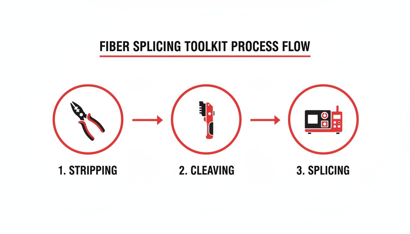
As you can see, it’s a simple progression: strippers, cleaver, and then the splicer. Each tool has a specific, essential role.
For a mechanical splice, the prep is identical. But instead of fusing, you insert the cleaved ends into a small splice body. Inside, a clever mechanism aligns the cores, and an index-matching gel fills the tiny air gap between them. Once you activate the clamp or cam, the fibers are locked in place, and the connection is complete.
Protecting Your Work for the Long Haul
A freshly spliced fiber is incredibly fragile. The final step is to protect it, and rushing this is a rookie mistake. Proper protection ensures your work will last for decades inside a splice closure, surviving moisture, temperature changes, and vibration.
Here’s a crucial habit: before you even start stripping, slide a heat-shrink splice protection sleeve onto one of the fibers. After a good fusion, you’ll slide that sleeve and center it over the bare glass. This sleeve has three key parts:
- An outer tube that shrinks with heat.
- An inner tube with an adhesive liner that melts to create a moisture-proof seal.
- A tiny steel or ceramic rod that gives it rigidity.
Once it's positioned, the whole assembly goes into the splicer's built-in heat oven. The machine cooks it for a moment, shrinking the sleeve and melting the liner to create a single, tough unit that restores the fiber's strength. The last move is to carefully place the protected splice into a splice tray, making sure to route the fiber gently without any sharp bends.
The demand for this kind of precise work is massive. The global market for optical fiber splices was valued at around USD 1.5 billion in 2023. Meanwhile, the market for the splice closures that house this work is expected to hit USD 4.8 billion by 2035. That's a direct reflection of the millions of splices being made to build out the FTTH, 5G, and data center networks we all rely on.
Mastering every one of these steps—from opening the cable to seating that final splice in its tray—is what separates an amateur from a professional. It's this attention to detail that forms the backbone of successful fiber optic construction and guarantees a network that performs reliably for years to come.
How to Test and Verify Your Splice Quality

A splice might look perfect on the splicer’s screen, but that’s only half the story. The real proof is how it performs under network traffic. For any professional, testing isn't just a recommendation; it's a non-negotiable step that provides the hard data to guarantee network integrity and meet performance standards.
Don't get me wrong, the fusion splicer’s loss estimate is a great first check. But it’s just that—an estimate. It can't see problems further down the line or truly characterize the splice's performance. For that, you need to break out the dedicated test gear.
Using an OTDR to Characterize a Splice
The gold standard for verifying a splice is the Optical Time Domain Reflectometer, or OTDR. Think of an OTDR as radar for your fiber optic cable. It shoots a powerful pulse of light down the fiber and then listens for the reflections that bounce back. By analyzing the timing and strength of this reflected light, it paints a graphical "trace" of the entire cable run, showing you exactly what’s happening at every point.
This trace lets you zoom in on the precise location and performance of your splice. A well-executed fusion splice should appear as a tiny, sharp drop on the trace, which signals very low signal loss. Industry standards typically demand a fusion splice loss below 0.1 dB, but most seasoned technicians I know won't sign off on anything over 0.05 dB.
Here’s a great example of what an OTDR trace looks like. It visually maps out every event along a fiber link.
As you can see, the OTDR displays events like connectors (the reflective spikes) and splices (the non-reflective drops) over distance. This allows you to measure the loss at each specific point with incredible accuracy.
A bad splice, on the other hand, shows up as a much larger drop or, even worse, a reflective "spike" right before the drop. That spike is a dead giveaway for a problem like a bad cleave, contamination, or an air gap that's causing light to bounce back toward the source—a nasty issue we call back reflection.
The OTDR doesn't just tell you if a splice is bad; it helps you diagnose why. A big loss event with no reflection usually points to core misalignment. A reflective event, however, suggests a physical problem right at the splice point, like a chipped cleave.
Simpler End-to-End Loss Testing
Sometimes, a full OTDR trace is overkill, especially for shorter runs or quick field verifications. In those scenarios, an Optical Light Source and Power Meter (OLSPM) is your best friend. This two-part tool gives you a simple but reliable end-to-end loss measurement for the entire link.
The process is refreshingly straightforward:
- Hook up the light source to one end of the fiber.
- Connect the power meter to the other end.
- The source sends a stable light signal with a known power level.
- The meter on the far end measures how much of that power actually arrived.
The difference between the power sent and the power received is your total link loss, measured in decibels (dB). While this method won’t isolate the loss of your specific splice, it’s a fast way to confirm the overall health of the line you just worked on. If the total loss falls within the acceptable "loss budget" for that link, you know your splice did its job.
What the Test Results Tell You
Learning how to read your test results is just as important as learning how to splice fiber optic cable. The data tells a clear story about the quality of your work.
- Low, Non-Reflective Loss: This is what you're aiming for. It's the signature of a perfect fusion splice where the fibers are fused into a nearly seamless path for light.
- High Loss: This is a red flag. High loss almost always tracks back to a mistake in your prep work—a dirty fiber, a poor cleave, or using the wrong splicer program for the fiber type.
- Reflective Events: High reflectance is especially damaging to network performance because it can disrupt the transmitters. It’s typically caused by air gaps, which you’ll find in poorly made mechanical splices or seriously flawed fusion splices.
Ultimately, testing is your quality control. It’s the final step that proves your splice is more than just a connection—it's a seamless extension of the optical path, built to carry critical data reliably for years.
Troubleshooting Common Fiber Splicing Problems
Even the most seasoned tech runs into a splice that just won't pass. You've done everything by the book, but the OTDR screams "failure" with a massive loss event, or the splicer itself throws an error code. Don't sweat it. This is a normal part of the job, and knowing how to quickly diagnose the problem is what separates the pros from the novices.
Frustratingly high loss readings almost always come down to a handful of common culprits. Before you start questioning your skills, run through a mental checklist. More often than not, the problem is in the prep work, not the machine.
Diagnosing High Loss Readings
I can tell you from experience: the number one cause of a failed splice is a poor cleave. A chipped, angled, or otherwise imperfect fiber end makes a low-loss fusion physically impossible. Your high-precision cleaver is a delicate instrument, and its blade can get dull or dirty over time.
Contamination is another frequent offender. A microscopic speck of dust in the splicer’s V-grooves can throw off the alignment just enough to ruin the splice. The same goes for any residual oil or debris on the fiber itself—it’ll just burn up during the fusion process and create a bubble that wrecks the light path.
Before you do anything else, check these things first:
- Your Cleaver Blade: Is it dirty? Chipped? A quick wipe with isopropyl alcohol might be all it needs. If it’s dull, rotate the blade to a fresh position. Most cleavers give you 16 different positions for exactly this reason.
- Your Splicer's V-Grooves: Grab a cleaning swab and some alcohol and meticulously clean the grooves where the fibers sit. A quick blast of canned air can help dislodge any stubborn particles.
- Your Cleaning Process: Are you using fresh, 99% IPA and truly lint-free wipes? Reusing a wipe or using a cheap solvent can actually introduce more gunk than it removes.
If you’ve sorted these issues and you’re still seeing high loss, it’s time to look at your splicer’s settings.
An arc check isn't just for routine maintenance; it's a critical calibration tool. Environmental factors like temperature, humidity, and even altitude can change the electric arc's intensity. Running a quick arc check calibrates the machine to the current conditions, ensuring it delivers the perfect amount of heat for a clean fusion.
Decoding Splicer Errors and Visual Defects
Modern fusion splicers are incredibly smart. They give you a ton of diagnostic information right on the screen, from error messages to a visual inspection of the finished splice. Learning to read these clues is the key to efficient troubleshooting.
When you look at a splice on the screen, you might see several common defects. Each one points to a specific problem with your prep work or the machine's calibration.
Here’s a quick field guide to what you might see:
| Visual Defect | What It Looks Like | Likely Cause(s) |
|---|---|---|
| Bubble or Inclusion | A dark spot or bubble trapped inside the splice. | Dirty fiber; contamination got burned during the arc. |
| Thick Line or Shadow | A dark, thick line right at the splice joint. | A bad cleave (angled or chipped); severe core misalignment. |
| Fattening or Bulge | The splice point is noticeably thicker than the fiber. | Arc power is too high or the arc duration is too long. |
| Neck-Down or Thinning | The splice point is noticeably thinner than the fiber. | Arc power is too low or the fibers were pushed together too far. |
For instance, if you keep seeing a "fat" splice, your machine might be pushing the fibers together too aggressively, or the arc current is just too high for that particular fiber. Don't just keep re-splicing and hoping for the best. Take a moment to adjust one variable at a time. Systematically lower the fusion current or duration slightly and see if the defect goes away.
Learning how to splice fiber optic cable is as much about troubleshooting as it is about following the steps. By recognizing these common failure points and systematically working through them, you can turn a frustrating failed test into a quick fix, saving a ton of time and ensuring a rock-solid network connection.
Common Questions from the Field
Even with a step-by-step guide, real-world situations always bring up new questions. It's one thing to read the manual, but it's another thing entirely to be out in a truck, trying to get a connection just right. These are the kinds of practical queries I hear all the time from technicians, both new and experienced.
Let's clear up some of the most common points of confusion you'll run into on the job.
How Long Does a Single Fiber Splice Really Take?
This is the classic "it depends" scenario, but I can give you some realistic numbers based on years in the field. For a skilled tech working in a controlled environment like a splicing van, the actual act of fusion splicing—from stripping the fiber to shrinking the protection sleeve—is pretty quick. You're looking at about three to five minutes per fiber.
But that's just one small part of the job. The real clock starts ticking the moment you crack open the splice enclosure.
- Closure Prep: Just getting into the enclosure and preparing it can take anywhere from 15 to 30 minutes, especially if it's an older, weathered unit.
- Routing and Prepping Tubes: You have to carefully route the buffer tubes and expose the specific fibers you need, which can easily add another 10 to 20 minutes.
- Dressing the Splice Tray: Meticulously organizing the fibers in the tray is crucial for future access and long-term reliability. Rushing this step is a recipe for a future service call.
So, a more practical estimate for completing a single 12-fiber ribbon splice, including all the prep and cleanup, is closer to 45-60 minutes. A single loose fiber might be a bit faster, but efficiency comes from a smooth, practiced workflow, not by cutting corners on the critical steps.
What's the Real Cost Difference: Fusion vs. Mechanical?
When you’re planning a project, the cost difference between fusion and mechanical splicing really comes down to a choice between upfront investment versus long-term operational costs.
Fusion Splicing: The initial buy-in is steep. A good quality fusion splicer is a major piece of equipment, costing anywhere from $5,000 to well over $15,000. After that initial hit, though, the cost per splice is next to nothing—the protection sleeves are often less than a dollar apiece.
Mechanical Splicing: Here, the upfront cost is tiny. You can put together a basic mechanical splicing toolkit for just a few hundred dollars. The catch is the per-splice cost, which is much higher. Individual mechanical splices will run you anywhere from $10 to $30 each.
The math is pretty clear. For any large-scale project with hundreds or thousands of splices, fusion is the only way to go. The high equipment cost is quickly absorbed by the rock-bottom price of consumables. Mechanical splicing still has its place, though—it’s the champion for quick, low-volume emergency repairs where getting a link back up fast is more important than the cost per connection.
Can You Splice Different Types of Fiber Cables Together?
This is a fantastic question, and the answer is a firm "yes, but you really need to know what you're doing." You can physically join almost any two glass fibers, but whether that connection will actually pass traffic depends entirely on the fiber core sizes.
- Single-Mode to Single-Mode: No problem. Splicing different types of single-mode fibers, like a G.652D to a G.657A, works perfectly fine. Their core sizes are compatible.
- Multi-Mode to Multi-Mode: This gets tricky. Splicing a 50-micron core fiber to a 62.5-micron core is possible, but it’s going to introduce significant signal loss (attenuation). This is especially true when light travels from the larger core into the smaller one. It’s a bad idea for any network that needs reliable performance.
- Single-Mode to Multi-Mode: Never do this. Splicing a tiny 9-micron single-mode core to a massive 50 or 62.5-micron multi-mode core will cause catastrophic signal loss. It's like trying to pour a river into a garden hose—most of the light simply won't make it into the smaller core, and the link will be unusable.
The golden rule is simple: always splice like-for-like fiber types. Mismatched splices should only ever be a temporary fix in a true emergency, never a part of permanent network infrastructure. Getting this right is a fundamental part of splicing fiber optic cable like a professional.
When the performance of your network hinges on perfect connections, you need a team that treats every splice with expert care. Southern Tier Resources provides complete fiber optic services, from new construction to the most precise splicing and testing. Contact us today to make sure your infrastructure is built for ultimate reliability and peak performance.