Tuesday morning starts under a raised floor in a mid-sized colocation hall. Four technicians are staged beneath a four-post rack, a ladder is open, and a spool of Cat6A is feeding from the cart. The lead is studying a pathway conflict between new backbone routes and existing power whips. The foreman is chasing a delivery window for LC patch cassettes. Meanwhile, the project manager is rewriting the termination schedule because one crew member called out sick.
That scene is structured cabling installation as it happens. The work depends on cable selection, but schedules, labor availability, pathway decisions, labeling, testing, and handoff discipline usually determine whether the project finishes cleanly. A recent industry estimate values the global structured cabling market at USD 12.41 billion in 2024, with a projected increase to USD 26.30 billion by 2033, an 8.5% CAGR from 2025 to 2033 (Grand View Research market estimate). That scale makes installation execution a management problem as much as a technical one.
A Crew on a Raised Floor and Why This Guide Exists
The lead technician has three immediate choices. He can route around the power whips, wait for the electrical contractor to move them, or accept a pathway arrangement that will create access problems later. None of those choices belongs in a last-minute conversation under a rack. Each should have been resolved during design coordination, before cable, labor, and lift time were committed.
The foreman's missing LC patch cassettes create a different kind of delay. The cable pull might continue, but the crew can't complete the planned termination sequence. That forces technicians onto another task, separates pulling from termination, and makes the original labor plan less useful by the hour. A sick call can have the same effect when a schedule has no float and every technician is assigned to a narrow task.
Practical rule: If the crew discovers a design decision while pulling cable, the project is already paying for that decision twice.
The industry has changed since commercial building cabling became more standardized in the late 1980s and early 1990s. TIA/EIA-568 and related performance rules established a common architecture for backbone and horizontal cabling, telecommunications rooms, and performance categories (background on structured cabling standardization). That common architecture helps different vendors' components work within a predictable installation and testing framework. It also gives project teams a shared language for scope, inspection, and acceptance.
The labor constraint is just as important. Industry coverage identifies a technician shortage of roughly 250,000 workers, while the same market reporting says data centers account for over 41% of global structured cabling installations and describes a rapid demand increase from AI and hyperscale construction (Astute Analytica market coverage). When qualified technicians are scarce, poor sequencing doesn't just inconvenience the crew. It can leave the right work waiting for the wrong person.
This guide focuses on the controls that keep a build moving: site readiness, staged materials, clear handoffs, disciplined installation, certification, and documentation. Cable categories matter, but a technically correct design still fails commercially if the crew can't access the pathway, locate the correct port, or produce a usable closeout package.
What Structured Cabling Actually Means
Structured cabling installation is the construction of an organized, standards-based physical plant made from cable, pathways, patch panels, termination hardware, racks, cabinets, and work-area outlets. The plant can support voice, data, video, and low-voltage building services through a planned architecture rather than a collection of isolated runs.
The architecture is commonly described through six subsystems:
- Entrance facility: The point where service-provider cabling enters the building and connects with the premises infrastructure.
- Equipment room: The primary location for major network equipment, cross-connects, and central distribution.
- Backbone cabling: The routes connecting entrance facilities, equipment rooms, and telecommunications rooms.
- Telecommunications room: The distribution point where backbone and horizontal cabling are terminated and managed.
- Horizontal cabling: The permanent link extending from a telecommunications room toward outlets and service locations.
- Work area: The endpoint where patch cords connect outlets to computers, phones, access points, cameras, or other devices.
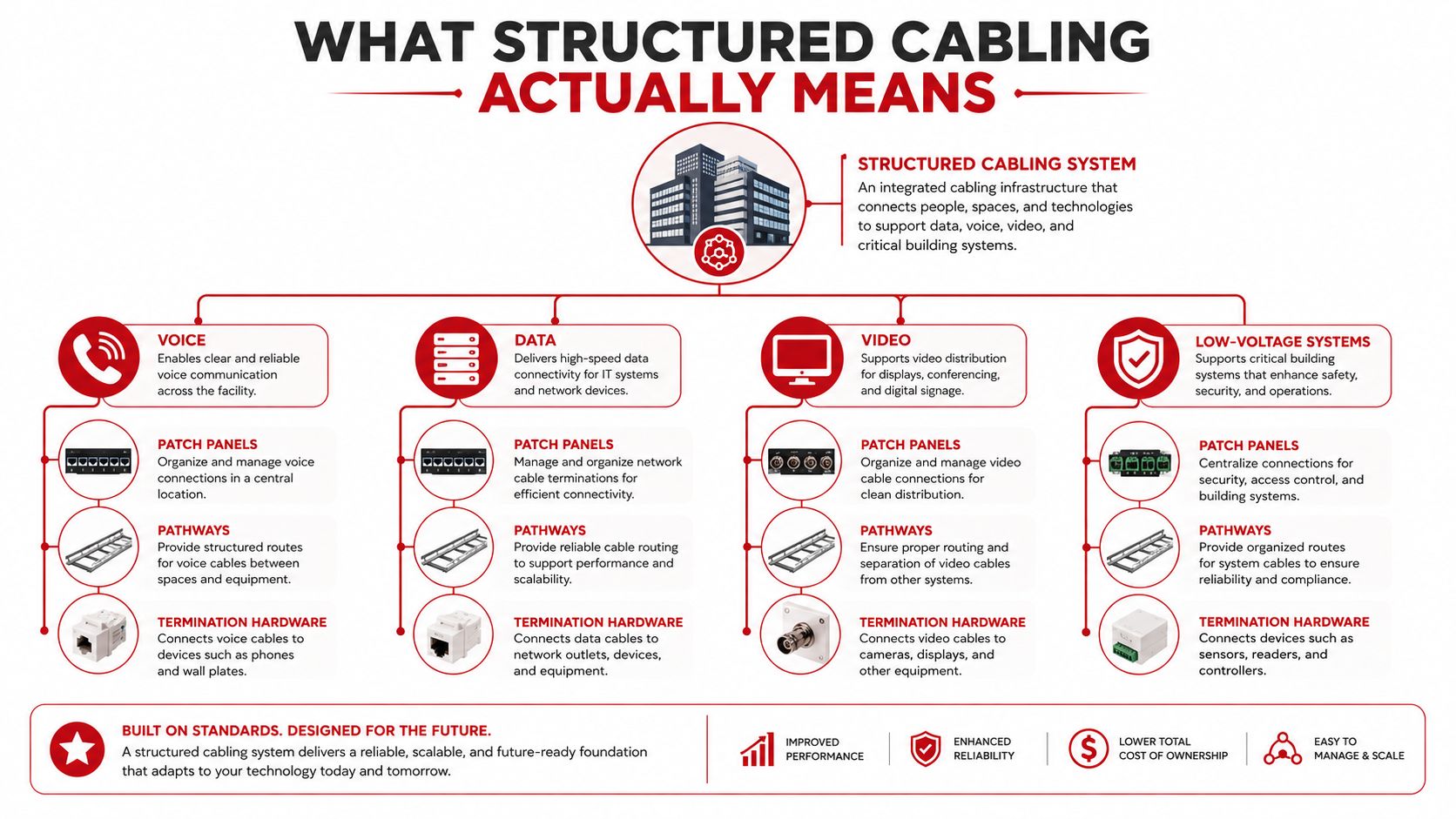
The difference from point-to-point wiring is easier to explain operationally than technically. In a point-to-point arrangement, equipment is connected directly to other equipment wherever a path can be found. In a structured system, permanent cabling terminates in organized distribution hardware, while shorter patch connections handle changes at the rack or outlet. The first approach can appear fast on a small installation, but it becomes difficult to trace, expand, and protect as devices accumulate.
The standards provide more than a preferred layout. TIA-568 and ISO/IEC 11801 establish common expectations for architecture, media, connection methods, and performance verification. That gives the owner a repeatable baseline for testing and gives different crews a way to work on the same plant without relying on tribal knowledge.
Today's media choices usually divide by environment and distance. Category 6A copper commonly serves horizontal connections and equipment that needs power delivery over twisted pair. OM3, OM4, and OM5 multimode fiber appear in shorter, high-density backbone and data center applications. OS2 singlemode fiber supports longer-distance backbone and campus connections. The correct choice depends on the application, pathway, equipment, distance, and future operating plan, not on the highest specification listed in a catalog.
Planning the Build Before Anyone Pulls Cable
A clean installation starts with a drawing review that is specific enough to expose field conflicts. The project team should compare the cabling scope against the latest architectural, electrical, mechanical, fire protection, reflected ceiling, and equipment drawings. Old plans create false certainty. A pathway shown as available may already be occupied, a sleeve may have moved, or a rack elevation may no longer match the floor layout.
Resolve pathway and access constraints
Begin with the physical route. Check conduit fill, ladder-rack capacity, basket-tray space, access clearances, and transitions between rooms. Calculate whether the proposed cable bundle can enter, turn, and exit without exceeding the cable manufacturer's bend-radius requirements. A pathway that technically holds the cable may still be unusable if the crew can't dress it, inspect it, or add future runs.
Keep communications pathways separated from power and other electromagnetic sources in accordance with the project's applicable TIA-569 requirements. Plan firestop locations before mobilization, then align inspections and approvals with the authority having jurisdiction. Firestop work left until the end often becomes a scheduling trap because ceiling closeout, inspection access, and other trades' work may already be complete.
Lock details that crews need at the work face
The following decisions should be closed before the first box is opened:
- Rack elevations: Confirm cabinet positions, patch-panel heights, vertical managers, grounding points, and floor-tile cuts against the current room layout.
- Sleeves and cores: Verify each penetration against the latest field condition and record the result in the project's as-built process.
- Service loops: Define where slack belongs, how much is practical for the equipment, and how it will be supported without creating a coil that blocks airflow or access.
- Materials: Sequence cable, panels, jacks, cassettes, splice hardware, labels, hangers, firestop materials, and test equipment so the next task isn't waiting on a delivery.
- Labels: Approve the site-specific identification scheme, including the applicable TIA-606 class, before pulling begins.
Relocation projects need the same discipline. A practical business IT relocation checklist can help coordinate equipment moves, shutdowns, access, and technology dependencies around the cabling sequence.
Run a day-one readiness check
The crew lead should verify approved drawings, access permits, pathway completion, safety requirements, material counts, labeling stock, test-equipment calibration, pull paths, room readiness, and trade coordination before assigning tasks. If any answer is unclear, the right action is to log the constraint and assign an owner, not send technicians into the pathway hoping the issue resolves itself.
Running the Physical Install on Site
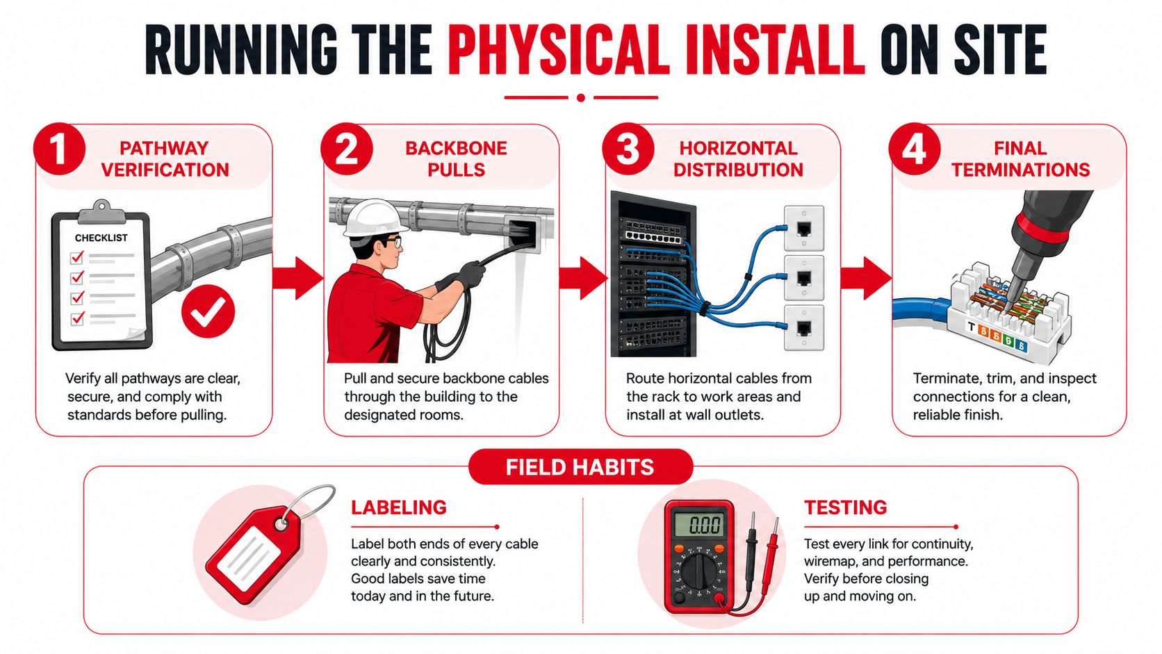
The physical work should move through controlled phases, with each phase producing a usable handoff. The next crew shouldn't inherit a pathway full of unmarked cable, unverified routes, or unresolved damage.
Start with the pathway
Pathway verification comes first. Inspect conduit interiors, pull strings, tray supports, sleeves, fire-rated penetrations, access points, and separation from power. Confirm fill before pulling. A route that looks open from the floor can narrow at a bend, become inaccessible above a finished ceiling, or conflict with another trade's planned installation.
Backbone pulls follow only after the route is accepted. Use appropriate pulling equipment and lubricant for long or difficult runs, control tension, and protect cable jackets at bends and entries. Assign one person to manage the reel and another to watch the pull path when the route demands it. Label the cable at the pull, not at the end of the shift, while the source and destination are still known.
Distribute horizontal cable without losing control
Horizontal distribution is repetitive, which makes it vulnerable to shortcuts. Keep bundles supported, preserve bend radius at every transition, and use hook-and-loop fasteners where later movement is expected. Tight zip ties can deform cable jackets and create problems that won't be obvious from a visual inspection.
Stage materials close to the work face, but don't turn the room into a storage area. Patch panels, jacks, labels, cable supports, and termination tools should arrive in the sequence the crew will use them. A technician who spends the morning searching for hardware is not creating useful production, even if the labor is charged to the project.
Treat copper and fiber differently
Copper installation depends on controlling pair geometry during termination. Keep untwist within the manufacturer's limits, avoid excessive jacket removal, and maintain a clean, repeatable dressing pattern at the panel and outlet.
Fiber demands a stricter contamination routine. Protect connectors and end-faces with caps, clean and inspect multifiber connectors before mating, and keep inspection records with the link documentation. Pre-terminated assemblies can reduce field termination work, but they still require careful routing, slack management, polarity control, and protection during installation.
Field control: A cable that isn't labeled, supported, and protected when installed becomes someone else's troubleshooting problem.
Multiple crews need explicit handoffs. The backbone team should identify completed routes and exceptions. The horizontal team should receive accepted pathway zones. The termination team should receive labeled cable ends and a current port schedule. Before another trade closes a ceiling, the cabling supervisor should inspect the work, photograph concealed routes where required, and record deviations.
Testing, Certification, and Sign-Off
Testing isn't an administrative afterthought. It is a production phase with labor, equipment, access, troubleshooting, and retest time in the schedule. Industry reporting cites field data indicating that roughly 57% of new network cabling fails certification on the first test, with improper terminations identified as the most common cause (industry field reporting on certification failures). The practical response is to test every link, isolate failures quickly, correct the physical cause, and retest against the same identifier.
Copper certification checks more than continuity. A standards-based test set evaluates wire map, length, insertion loss, return loss, NEXT, PSNEXT, ACRF, and propagation delay. These measurements expose different problems, including reversed pairs, excessive loss, poor terminations, impedance discontinuities, crosstalk, and timing behavior. A link can pass a basic continuity check and still fail a performance requirement.
Fiber certification has its own sequence. Tier 1 uses a light source and power meter to measure attenuation. Tier 2 uses OTDR traces to identify events such as splices, connectors, reflections, or abnormal loss. Connector inspection with a microscope is essential because a contaminated end-face can compromise a link even when the cable route and splice work appear correct.
| Media Type | Key Tests | Equipment Required | Standard Reference |
|---|---|---|---|
| Copper | Wire map, length, insertion loss, return loss, NEXT, PSNEXT, ACRF, propagation delay | Copper certification tester, permanent-link adapters, calibration records | TIA-568 and ISO/IEC 11801 |
| Fiber | Attenuation, insertion loss, connector inspection, OTDR event analysis | Light source, power meter, OTDR, fiber inspection microscope | Applicable fiber requirements under TIA-568 and ISO/IEC 11801 |
The testing workflow should tie every result to the cable ID, panel, port, room, and tester file. Failed links need a documented cause, corrective action, and retest result. Don't accept a verbal assurance that a termination was redone. The report should show that the link passed after the correction.
Acceptance standard: If the client can't match a test result to a labeled physical link, the project isn't ready for sign-off.
Closeout should include current test reports, tester calibration records, approved exceptions, and an open punch list. The client should sign acceptance only after the team has reviewed failures, retests, access restrictions, and any work intentionally deferred to a later phase.
Field Pitfalls That Bite You After Handoff
A green test result at installation doesn't guarantee a reliable link after months of moves, adds, maintenance, and contact with other trades. The weak points often appear at interfaces, especially where a technician rushed a termination or treated a connector as indestructible.
Copper pairs can be untwisted too far at the jack or patch panel. The link may appear neat, but the disturbed geometry can affect performance under a demanding application. The control is simple, although it requires discipline: strip only what is necessary, preserve the pair twist, use compatible termination hardware, and inspect the finished work before certification.
Fiber failures often begin with end-face contamination. A connector can be clean when the system is accepted and dirty after a move or patch-panel change. Keep dust caps installed when ports are unused, clean before mating, and inspect when troubleshooting rather than repeatedly reseating the same connector.
Small installation shortcuts create long service calls
Cable management causes its own delayed failures. Tight plastic ties can compress jackets, bend-radius violations can create intermittent errors, and unsupported vertical runs can sag onto ceiling grid or other infrastructure. Industry guidance specifically warns about contamination, micro-bending, pathway separation, and overly tight bindings, and recommends irregularly spaced, loosely fitted bindings so cables remain movable (data center structured cabling guidance).
Use dedicated tray paths, proper bend-radius hardware, and hook-and-loop fasteners where adjustment is likely. Keep power and fiber in appropriately separated pathways. Patch cords deserve the same scrutiny as permanent links. A certified installation can be undermined by cords of unknown construction or quality, so maintain a documented approved-cord list and replace questionable cords instead of treating them as harmless accessories.
The system includes the label, support, connector, patch cord, and record. A crew that hands over a tidy rack but no approved-cord policy or change documentation has delivered an incomplete operating environment.
Documentation, As-Builts, and a Clean Handoff
Closeout is the first operational tool the client uses after the installers leave. The package should let a technician stand in a telecommunications room, scan a label, find the corresponding port and drawing, and understand the tested path without reconstructing the project from email threads.
Build the package around physical identification
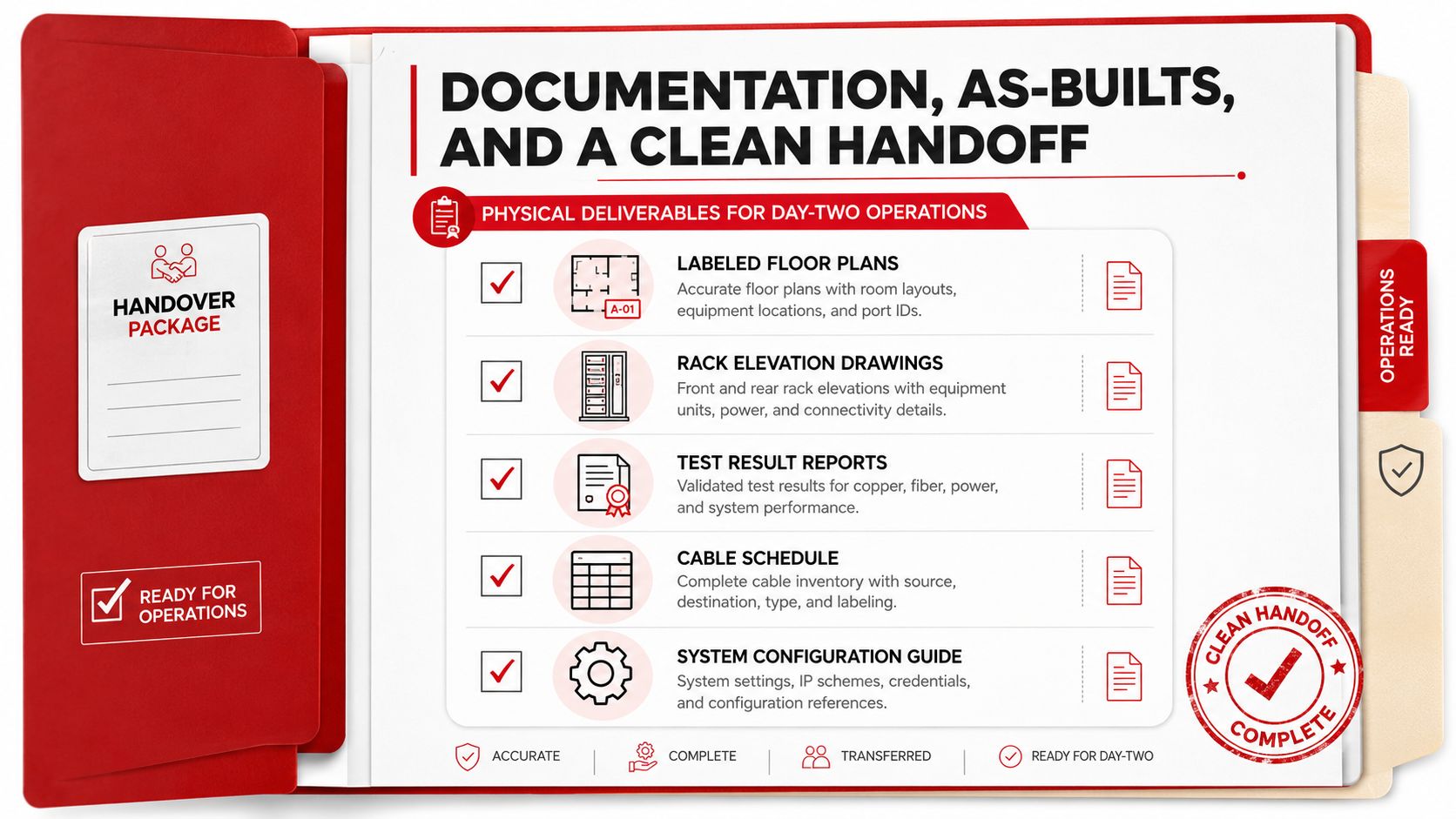
At minimum, provide:
- Labeled floor plans: Show room locations, outlets, pathway routes, and port-level IDs.
- Rack elevations: Record cabinet positions, patch panels, managers, cassettes, and equipment interfaces.
- Test reports: Include copper attenuation, NEXT, return loss, and related certification results, plus fiber insertion-loss records and OTDR traces.
- Patch-panel schedules: Match panel, port, cable ID, destination, service, and status.
- As-installed materials: Reconcile the bill of materials with what the crew installed, including substitutions and approved deviations.
A useful cable number normally identifies the building or area, room, rack, panel, and port. The exact format should fit the site, but it must remain unique and readable at both ends. Labels that rely on a technician remembering a spool number or installation sequence won't survive a later move.
Make the O&M file usable
The operations and maintenance package should include warranty certificates, manufacturer specification sheets, tester calibration records, approved submittals, firestop records, change logs, and punch-list sign-off. Store the files in a location the client can access after the project team has demobilized. If a software platform manages labels, test results, or asset records, transfer the required credentials and ownership instead of leaving the system tied to a contractor account.
The project manager's final walkthrough should be deliberate:
- Walk every telecommunications room, equipment room, and accessible work area with the client.
- Demonstrate label identification and any scan-based lookup process.
- Confirm that test reports and as-builts are uploaded and searchable.
- Review open items, approved deviations, and warranty exclusions.
- Confirm the warranty start date and the process for service requests.
Handoff principle: The client shouldn't need the original foreman to explain the system on day two.
Southern Tier Resources offers engineering, construction, testing, documentation, and maintenance for fiber-based communications infrastructure and data center fit-outs, including structured cabling-related work. If your next build needs a partner that can coordinate field installation with disciplined testing and as-built delivery, visit Southern Tier Resources to discuss the scope, schedule, and handoff requirements.