

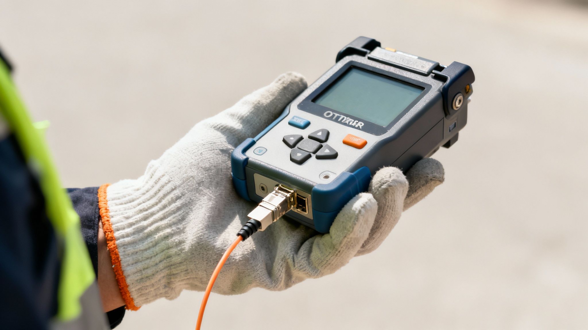
At its most basic, you can think of OTDR testing like sending a radar or sonar pulse down a fiber optic cable. It’s a technique used to create a detailed, virtual map of everything happening inside that strand of glass. An Optical Time Domain Reflectometer (OTDR) is the specialized instrument that makes this possible. It shoots a very specific pulse of light into the fiber and then meticulously analyzes the light that scatters or reflects back.
This process gives technicians a remarkable ability to "see" inside the cable from a single connection point, revealing its entire journey.
Reading Your Network’s Health Report
An OTDR provides a complete "birth certificate" for every fiber link. It establishes a performance baseline that becomes invaluable for the entire lifespan of your network. By interpreting the data from that returning light pulse, a skilled technician can uncover a wealth of information about the fiber's condition.
This isn't just about finding problems; it's about verifying quality and planning for the future. The data is crucial for:
- Certifying new installations to prove they meet performance specs right from the start.
- Troubleshooting network outages by quickly and precisely locating the exact source of a problem.
- Performing preventative maintenance to spot degrading components before they cause a catastrophic failure.
Pinpointing Every Connection and Flaw
An OTDR test measures the total length of the cable run, calculates the overall signal loss (known as attenuation), and pinpoints the exact location of every event—splices, connectors, sharp bends, or even breaks. This detailed characterization helps verify the quality of the installation work and the integrity of the physical infrastructure. It’s particularly vital for understanding the quality of unlit infrastructure like dark fibre networks.
So, what is OTDR testing in simple terms? It’s the method of creating a loss-versus-distance profile by injecting controlled optical pulses into a fiber. This creates a virtual map showing every connection, splice, and fault along the cable's path.
Depending on the instrument’s power, this profile can stretch from 40–100 km or even more. Modern OTDRs are incredibly precise, capable of detecting events with resolutions down to a meter or less, making them indispensable for qualifying today’s dense metro rings and demanding 5G infrastructure.
The table below breaks down the key information an OTDR provides and why it's so important for network owners.
Key OTDR Testing Capabilities at a Glance
| Capability | What It Measures | Why It Is Important for Network Operators |
|---|---|---|
| Distance Measurement | The total length of the fiber optic cable run. | Verifies cable routing, confirms physical path lengths, and helps in asset management and future planning. |
| Event Location | The precise location of connectors, splices, and faults. | Drastically reduces truck roll time and repair costs by pinpointing the exact spot of a break, bend, or bad splice. |
| Loss Measurement | The amount of signal strength lost at each event. | Ensures every connection and splice meets industry standards (like TIA/EIA), guaranteeing optimal network performance. |
| Reflectance Measurement | The amount of light reflected back from an event. | Identifies poor connections or unterminated ends that can cause instability and degrade high-speed data transmission. |
| Attenuation (Fiber Loss) | The gradual loss of signal strength along the fiber itself. | Confirms the quality and health of the fiber cable, ensuring it can support the required data rates over its full length. |
Ultimately, this detailed picture confirms that every component is working as it should.
Proper testing and documentation, like the expert fiber network services provided by our team, ensure every link is built for long-term reliability and peak performance from day one.
How an OTDR Creates a Picture of Your Fiber
Let's start with a simple analogy. Imagine you're standing at the edge of a deep canyon and you shout into the void. A few moments later, you hear echoes bouncing back—some are faint and distant, while others are sharp and loud, telling you where the canyon walls are.
An OTDR works on a similar principle, but it uses light instead of sound. It sends a powerful, high-intensity pulse of laser light down one end of a fiber optic cable. This pulse is like your shout, and the OTDR "listens" for the "echoes" that come back, painting a detailed picture of the entire fiber path.
As that pulse of light travels down the glass core, a very small, predictable amount of light naturally scatters in all directions. A tiny fraction of that scattered light heads right back to the OTDR's detector. This faint, continuous return signal is a phenomenon called Rayleigh scattering, and it forms the baseline of the OTDR's measurement—it's the background hum of the fiber itself.
Identifying Events with Light Echoes
What the OTDR is really listening for, though, are the loud echoes. When the laser pulse hits an "event"—anything that interrupts the light's smooth journey—a much larger amount of light is reflected back to the source. These events are the landmarks on our fiber map.
An event can be a normal part of the network architecture or a serious problem. Common events include:
- A pair of mated connectors
- A fusion or mechanical splice
- A sharp bend in the cable (a macrobend)
- A crack or a complete break in the fiber
Each type of event has a unique signature on the OTDR trace. A good, clean splice might show up as just a small drop in signal with almost no reflection. A dirty connector or a clean break in the fiber, on the other hand, will send back a huge spike of reflected light.
Translating Time into Distance
This is where the real magic happens. The OTDR's genius lies in its ability to pinpoint the location of these events by precisely measuring time. Its internal clock starts the second the laser pulse is sent and measures the exact time it takes for the light echoes—both the faint backscatter and the strong event reflections—to return to the detector.
Since the speed of light in glass is a known, constant value, the OTDR can run a simple calculation: Distance = (Speed of Light × Time) / 2. We divide by two because the measurement accounts for a round trip: light traveling down the fiber to the event and then all the way back.
This calculation happens thousands of times, plotting the strength of every returning signal against its calculated distance. The final result is a graph called an OTDR trace. This trace is essentially a visual map of the entire fiber link, showing a technician exactly where every connector, splice, and fault is located, turning an invisible network into a clear, actionable picture.
Learning to Read an OTDR Trace
The OTDR trace is the end result of the test—a graph that tells you the complete story of a fiber optic link. Getting comfortable with reading this graph is where the rubber meets the road, moving you from theory to a practical, hands-on diagnostic skill.
The trace itself is a simple plot. On the vertical (Y) axis, you have signal strength in decibels (dB). On the horizontal (X) axis, you have distance.
Think of it like a map of a cross-country road trip, where the line shows the elevation changes along your route. A smooth, gentle downhill slope is exactly what you want to see; it represents the natural, expected signal loss over distance. But sudden drops, sharp peaks, or weird flat sections? Those are landmarks that demand a closer look. Every little feature on this graph reveals something about the fiber’s health and the quality of the installation.
This visual below breaks down how an OTDR gathers the data to build this graphical story.
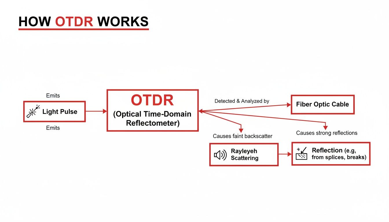
As the infographic shows, the OTDR sends a light pulse down the fiber. It then listens for the "echoes"—tiny amounts of light that are scattered back (Rayleigh scattering) and larger reflections that bounce back from specific points (Fresnel reflections). This return journey of light is what creates the trace.
Decoding the Key Features of a Trace
When you first pull up a trace, you'll notice a series of distinct patterns. Each one corresponds to a specific "event" or characteristic of the fiber link. Knowing these signatures is the foundation of accurate OTDR testing.
Here are the main features you’ll quickly learn to spot:
- The Initial Spike: The trace always kicks off with a massive spike. This isn't part of the cable you're testing; it’s the reflection from the OTDR’s own connector as it launches the light pulse. Right after this spike is a "dead zone" where the detector is temporarily overwhelmed, which is exactly why launch cables are non-negotiable for testing the very first connector of your link.
- The Downward Slope: A steady, gentle downward line is the signature of the fiber’s natural attenuation. This is the good, expected, gradual loss of signal as light travels through the glass. If you see a slope that’s too steep, it signals higher-than-normal loss, which could be from poor quality fiber or even physical stress on the cable.
- Sharp Vertical Drops: A small, sharp drop without a big reflective spike is typically a fusion splice. It shows a loss of signal (loss event) but very little reflected light. This is a good sign—it means the two fiber cores are cleanly aligned.
- Tall Reflective Spikes: A tall spike (reflective event) points to a spot where a significant amount of light is bouncing straight back. This is normal for connectors, but an unusually high spike could mean a dirty end-face, a bad mechanical splice, or even a crack in the fiber.
An OTDR trace is so powerful because it doesn't just tell you if there's a problem—it shows you what the problem is and exactly where it is. A sharp drop is loss; a high spike is reflection. It's that simple.
Distinguishing Good Events from Bad
Not every event on a trace is a fault. After all, connectors and splices are necessary parts of any network. The real skill is measuring the performance of these events against industry standards and project specifications.
For example, a good single-mode UPC connector should have a reflectance of -50 dB or better (meaning a more negative number). If you see a value closer to zero, like -30 dB, that indicates far too much reflection and a potential point of failure.
Similarly, the loss at a fusion splice should be minimal, often under 0.1 dB. A technician reading the trace can see in an instant whether a splice passes or fails. By learning these visual cues, you can assess the quality of an entire fiber link in minutes, pinpointing any issues with remarkable precision.
Where OTDR Testing Really Shines
Understanding the theory behind an OTDR trace is one thing, but seeing where it makes a real difference in the field is another. OTDR testing isn't just another diagnostic tool; it's a cornerstone of quality control, operational efficiency, and protecting major infrastructure investments.
Its value is clear across the entire lifecycle of a fiber optic network. From the moment a new cable spool arrives on-site to years of ongoing maintenance, this testing method provides the hard data needed to build reliable networks and keep them running at peak performance.
Construction and Network Certification
The most critical time for OTDR testing is during the initial build and certification of a new network. Before a single bit of data ever flows through it, every fiber link has to be verified against its design specs. An OTDR test at this stage creates a permanent "birth certificate" for the link.
This baseline documentation proves the installation quality is up to par and that all components meet performance standards. It confirms a few key things:
- Correct Splice Performance: Validates that fusion splices have minimal loss, ensuring signal integrity. You can find out more about what goes into a good connection by exploring our guide on how to splice fiber optic cable.
- Connector Quality: Measures the loss and reflectance of every connector pair, immediately flagging any that are dirty, damaged, or poorly seated.
- Total Link Integrity: Provides a complete map of the fiber path, confirming its length and making sure there's no installation-induced stress like tight bends.
Rapid Troubleshooting and Fault Location
When a network goes down, every minute counts. An OTDR is hands-down the most effective tool for rapidly locating the source of a problem. Instead of guessing or sending crews to multiple sites, a technician can shoot the fiber from one end and get an exact distance to the fault.
Whether it's a clean fiber cut from construction work, a degraded splice that finally gave out, or a failing connector, the OTDR trace points technicians right to the problem. This drastically cuts down the Mean Time to Repair (MTTR) and minimizes service disruptions for customers.
OTDR testing is the central pillar of fiber assurance for virtually every major network operator. It's the go-to tool for finding faults and monitoring performance across long-haul, metro, and access networks.
This isn't just an opinion; the industry data backs it up. OTDRs command a significant 36.9% share of the fiber optic test equipment market as of 2024. What's more, surveys show that over 61% of telecom providers depend on OTDRs for preventive diagnostics, using them to catch issues like micro-bends and bad splices before they cause a full-blown outage. You can dive deeper into this market data at Grand View Research.
Proactive Maintenance and Quality Assurance
Beyond new builds and emergency repairs, OTDR testing is a workhorse for routine maintenance. By comparing new traces to the original baseline documentation, technicians can spot gradual degradation over time.
A splice that's slowly failing or a connector that's getting dirty can be identified and fixed during a scheduled maintenance window, preventing a surprise outage down the road.
Finally, OTDRs are essential for acceptance testing on new cable reels from manufacturers. This simple QC step ensures the fiber meets spec before it gets put in the ground, saving a massive amount of time and money by avoiding the need to replace a faulty cable after it's already been installed.
Best Practices for Accurate OTDR Testing
Getting a trace from an OTDR is easy. Getting an accurate, reliable trace you can bet your reputation on? That takes discipline, a solid process, and a real understanding of what the machine is telling you.
The quality of your OTDR test results comes down to two things: setting up the instrument correctly and being methodical out in the field.
You can think of an OTDR a bit like a professional camera. Sure, you can leave it on "auto" and get a decent snapshot. But a real pro manually dials in the aperture, shutter speed, and ISO to capture the perfect image. In the same way, a skilled fiber technician needs to adjust critical OTDR parameters to pull a clean, meaningful trace from the noise.
Dialing in Your OTDR Settings
The two most important settings you'll need to master are Pulse Width and Averaging Time. These parameters have a direct impact on the detail and range of your test.
- A short pulse width is like a quick, high-resolution camera flash. It gives you incredible detail up close, letting you distinguish between two connectors that are very near each other. The trade-off is that its light doesn't travel very far down the fiber.
- A long pulse width is more like a powerful floodlight. It can illuminate the very end of a long-haul cable, but its broad beam can easily wash out the fine details and miss events that are close together.
Averaging time, on the other hand, determines how many individual measurements the OTDR takes and averages together. A longer time cleans up the signal, smoothing out the noise for a clearer trace, but it also means you're spending more time on each test. It's a constant balancing act between speed and precision.
Here's a quick guide to help you dial in the right settings for your specific job.
Essential OTDR Parameter Settings and Their Impact
| Parameter | What It Controls | Impact on Trace | When to Adjust |
|---|---|---|---|
| Pulse Width | The duration of the light pulse sent into the fiber. | Shorter pulses provide better resolution but less range. Longer pulses offer more range but lower resolution. | Use short pulses for premises/FTTH networks with closely spaced events. Use long pulses for long-haul routes. |
| Wavelength | The color of light used for the test (e.g., 1310nm, 1550nm). | Different wavelengths experience different levels of attenuation and are sensitive to different types of fiber stress. | Test at the same wavelengths the network will operate on. 1550nm is more sensitive to bends, while 1310nm is better for locating events. |
| Averaging Time | The duration the OTDR collects and averages data. | Longer averaging reduces noise, creating a smoother, more accurate trace, but increases test time significantly. | Increase for very long fibers or noisy environments to improve the signal-to-noise ratio (SNR). Use shorter times for quick checks. |
| Range | The maximum distance the OTDR will display on the trace. | Sets the horizontal (distance) scale of the graph. Setting it too short will cut off the end of the fiber. | Set the range to be at least 1.5 to 2 times the expected length of the fiber link to ensure the entire span and far-end events are captured. |
Choosing the right parameters isn't just a suggestion; it’s fundamental to getting a trace that accurately reflects the reality of the fiber link.
Field Procedures That Are Not Optional
Beyond the instrument settings, certain field practices are absolutely critical. If you skip these steps, your results will be compromised, no matter how perfectly you’ve configured the OTDR.
The first rule of OTDR testing is to always use launch and receive cables. Every OTDR has a "dead zone" right at its output connector where it's temporarily blinded by the powerful initial pulse of light. A launch cable—just a long spool of fiber—is connected between the OTDR and the link you're testing. This simple step pushes the dead zone into the launch cable itself, allowing the OTDR to see and accurately measure the crucial first connector of your actual network. A receive cable at the far end does the same for the last connector.
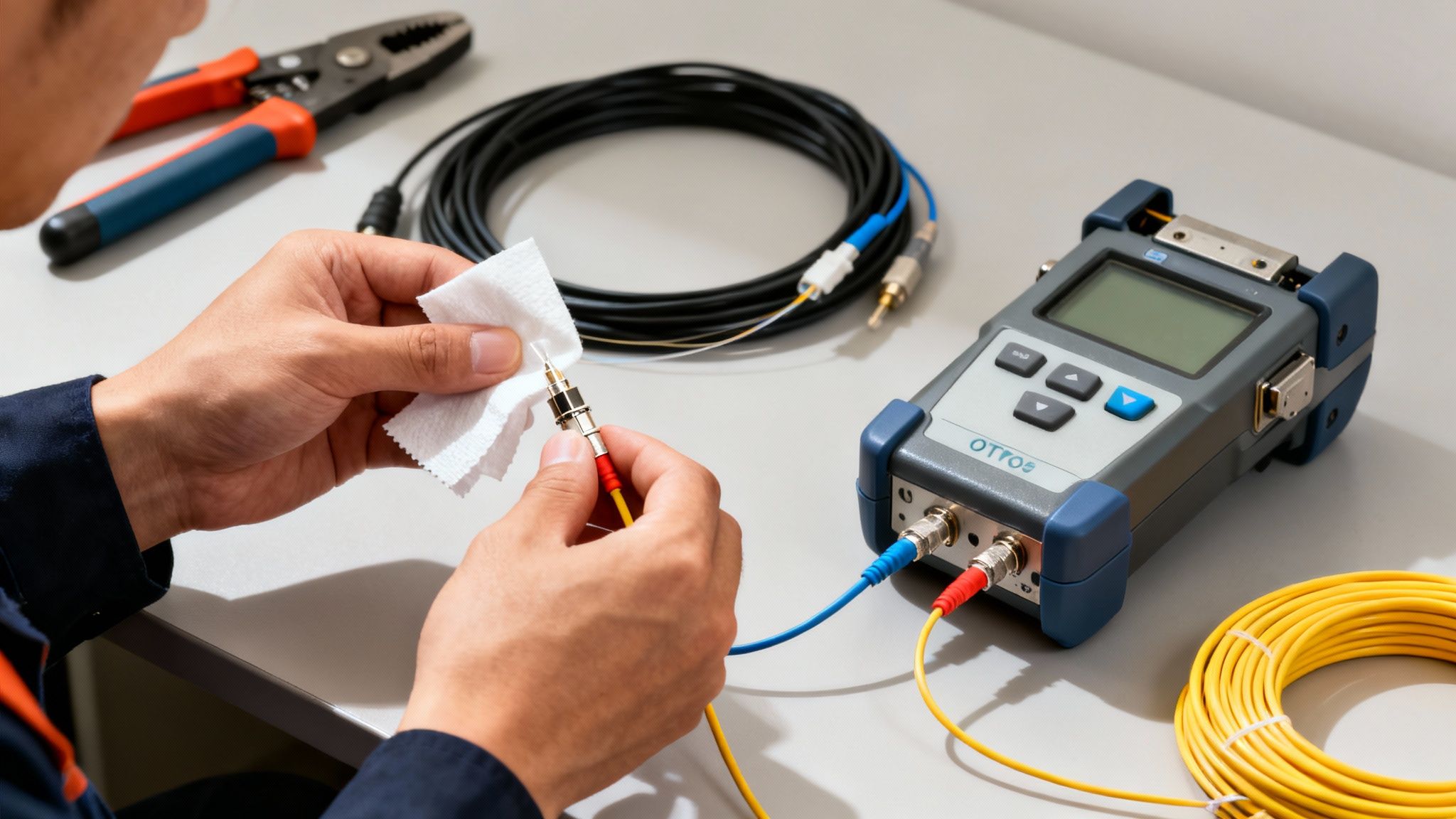
The single biggest source of network failures is a contaminated connector. Cleaning every single connector end-face before testing is not just a best practice—it's a requirement for professional-grade results. Even microscopic dust can create huge reflections and loss, leading to false failures.
Finally, you must work against clear pass/fail criteria defined by industry standards (like TIA/EIA) or the specific project's requirements. Knowing the maximum allowable loss for a splice or the acceptable reflectance for a connector before you start testing is essential. Following a structured process, like we outline in our guide on how to install fiber optic cable, ensures every link is validated against these important benchmarks.
Protecting your equipment is just as important. Sensitive test gear requires careful handling and the right environment, so it’s worth learning about professional ESD-safe workspaces and storage solutions to maintain the integrity and lifespan of your OTDR.
Common Questions We Hear in the Field
Even with a good handle on the theory, a lot of practical questions come up when you're actually out there using an OTDR. Let's tackle a few of the most common ones we hear from technicians and project managers.
What’s the Difference Between an OTDR and a VFL?
It helps to think of it this way: a Visual Fault Locator (VFL) is like a flashlight, while an OTDR is like a high-tech radar system.
A VFL is a simple, handy tool that shoots a bright red laser down the fiber. You can literally see the light bleeding through the jacket at a bad bend or a clean break, making it perfect for finding problems within a few feet of where you're standing.
An OTDR, on the other hand, is a powerful diagnostic machine. It gives you the full story—pinpointing the exact distance to a fault, measuring the specific signal loss at every splice and connector, and giving you a complete performance profile of a fiber link that could be miles long.
Why Do I Need to Use a Launch Cable?
Every OTDR has what's called a "dead zone" right at its connector. The initial blast of light from the test pulse is so powerful that it temporarily overwhelms the sensitive detector, blinding it for the first several meters of fiber.
Without a launch cable, you’d never get an accurate reading of the very first connector on the link you’re testing—which is obviously a critical connection.
By adding a launch cable (just a long, high-quality patch cord) between the OTDR and the fiber under test, you push that dead zone into the launch cable itself. This gives the detector the time and distance it needs to recover, so it can see and accurately measure that all-important first connection. For the same reason, a receive cable is almost always used at the far end to measure the final connector.
While an OTDR provides a great estimate of total link loss, the gold standard for certifying end-to-end signal loss is still an Optical Light Source and Power Meter (OLTS). The OLTS gives a more direct and precise measurement. For truly complete fiber certification, best practice is to use both.
When you need comprehensive fiber testing, clear documentation, and a network deployment you can count on, Southern Tier Resources is here to help. Discover our end-to-end infrastructure solutions at https://southerntierresources.com.