Structured cabling is a standardized, modular network infrastructure system that organizes voice, data, and fiber connections into predictable pathways, and it has been built on the ANSI/TIA-568 framework since 1991. In practice, that means a network can grow, change, and be repaired without turning every move or outage into a hunt through tangled cables.
If you're asking what is structured cabling, you're probably dealing with one of three situations right now. A new building needs network infrastructure before the walls close. An older server room has become a patch-cord thicket that nobody wants to touch. Or your team is planning an upgrade and realizes the risk isn't the switch or firewall. It's the physical layer underneath all of it.
That physical layer decides whether a new circuit can be turned up quickly, whether a failed link can be traced in minutes instead of hours, and whether the next expansion means adding capacity or ripping out what you already paid for. That's why structured cabling matters to carriers, enterprise IT teams, municipalities, and hyperscale operators alike. It turns cabling from hidden clutter into managed infrastructure.
What Structured Cabling Actually Means for Your Network
Walk into enough server rooms and you start seeing the same failure pattern. Patch cords drape across switch faces, old labels have peeled off, someone reused a cable path for a quick fix, and now one disconnected jumper takes out a phone system, a camera uplink, or a critical application port. The outage rarely starts with a dramatic hardware failure. It starts with confusion.
That's the problem structured cabling is meant to solve.

Order replaces improvisation
Structured cabling is an organized system of cables, connectors, patch panels, pathways, and termination points designed so signals travel through known, documented routes. Instead of running a separate cable every time a new device appears, you build a reusable framework. Devices change. The cabling plant stays understandable.
A simple way to think about it is this:
- Permanent cabling stays in place. The cable inside walls, ceilings, trays, conduits, and risers forms the long-term infrastructure.
- Short patch cords handle day-to-day changes. Technicians can reassign ports at the rack or outlet without disturbing the permanent link.
- Labels and records make every link traceable. You know where a run starts, where it ends, and what service it supports.
Practical rule: If a technician has to guess where a cable goes, you don't have structured cabling. You have wires.
It supports the network you have and the one you're building
People often hear "structured cabling" and think it means making a closet look neat. Clean racks are helpful, but benefit is operational. A properly designed system makes adds, moves, and changes predictable. It reduces accidental disconnects. It also gives planners room to scale bandwidth, add wireless access points, support security devices, or convert a copper-heavy design into a more fiber-centric one over time.
At Southern Tier Resources, that same logic applies whether crews are supporting a greenfield fiber build or a data center fit-out. The medium may differ, but the discipline is the same: route it intentionally, terminate it cleanly, test it, label it, document it.
Why readers often get this wrong
Many people confuse structured cabling with "the cables themselves." The cable matters, but structured cabling is really the system around the cable. The pathways, patching, room layout, labeling plan, cross-connect strategy, and test documentation are what make the installation maintainable years later.
That's why the best cabling is almost invisible during normal operations. Nobody talks about it when it works. They only notice when a rushed, undocumented install starts driving expensive rework.
Core Components of a Structured Cabling System
A good mental model is plumbing. Water doesn't reach a sink because someone ran random pipe across a building. It reaches the sink because the building has mains, risers, distribution lines, valves, and clearly defined endpoints. Structured cabling works the same way for signals.
From building entry to user outlet
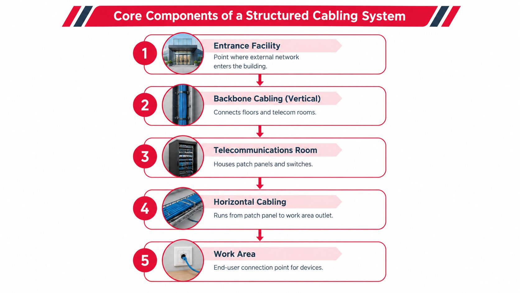
Most structured cabling systems are made up of a few core pieces working together:
- Entrance facility: The outside network enters the building. For a carrier or ISP, it's the handoff point between external plant and internal distribution.
- Backbone cabling: These are the vertical or inter-building links that connect major spaces such as equipment rooms and telecom rooms. Backbone paths often carry the highest-capacity links.
- Telecommunications room: The local distribution point, usually holding patch panels, switches, cable management, and terminations for a floor or area.
- Horizontal cabling: These runs go from the telecom room out to work-area outlets, cameras, phones, wireless access points, or other edge devices.
- Work area: The endpoint where users or devices connect into the system.
If you open a wiring closet and can identify those roles quickly, the network becomes much easier to manage.
Why patch panels matter more than people think
Patch panels are one of the most overlooked pieces in the whole design. They don't generate traffic, power devices, or light up dashboards, so they're easy to dismiss. But patch panels are what let you make changes without re-terminating the permanent cable.
Say an office desk moves, or an access control panel shifts to a new switch, or a wireless upgrade needs different port assignments. With a proper patching field, technicians move the service at the panel. They don't disturb the cable in the wall.
That separation between permanent infrastructure and temporary patching is what makes structured cabling modular.
The patch cord should be the sacrificial, replaceable part. The installed cable plant should not be what you're touching every time the business changes.
Layout and cable management are reliability issues
Racks, vertical managers, horizontal managers, ladder tray, and proper slack storage aren't cosmetic extras. They protect bend radius, reduce strain on terminations, and make troubleshooting possible under pressure.
For copper Ethernet, there is also a hard planning boundary. The practical constraint in ANSI/TIA-568-based structured cabling is the 100 m channel limit, including the permanent link and patch cords. Within that channel, performance depends on insertion loss, return loss, and crosstalk budgets. Technical guidance also notes that Cat 6A channels are engineered to support 10GBASE-T over the full 100 m channel, while return loss and alien crosstalk become more important as frequency rises, especially in dense data center environments, according to Quabbin's cabling channel reference.
Here's the practical takeaway in table form:
| Component | What it does | Why it matters |
|---|---|---|
| Entrance facility | Accepts external service into the building | Defines the clean handoff from outside plant to internal network |
| Backbone cabling | Connects major rooms or floors | Carries high-capacity traffic where failure affects many endpoints |
| Patch panels | Provide organized termination and cross-connects | Enable changes without disturbing installed cable |
| Horizontal cabling | Extends service to endpoints | Standardizes edge connectivity across offices and device areas |
| Cable management and racks | Support routing, protection, and access | Prevent damage, confusion, and service delays |
When people ask what is structured cabling, this is the answer they usually need. Not a bag of parts, but a system with roles, boundaries, and service logic.
Standards That Keep Structured Cabling Interoperable
The hidden strength of structured cabling is that it isn't reinvented from site to site. A contractor in one city, an equipment vendor in another, and an operations team years later can still work on the same infrastructure because the system follows shared rules.
The foundation was formalized in 1991
Structured cabling became a formal global industry standard in 1991, when the first ANSI/EIA/TIA-568 commercial building telecommunications wiring standard was published after work that began in 1985. Revisions followed in 1995, 2001, 2009, 2015, and 2020, creating the framework used for today's structured voice, data, and fiber deployments, as summarized in the ANSI/TIA-568 history overview.
That timeline matters because it explains why modern cabling systems can outlive several generations of electronics. Switches, wireless standards, and server hardware may turn over quickly. The cabling plant can keep serving new equipment if it was designed and installed to a consistent standard.
Standards reduce friction between people and products
In plain language, standards answer questions before a project starts:
- How long can a channel be
- How should components be organized
- What performance should a category of cabling support
- How should technicians administer and label the plant
- How should pathways and spaces be planned
Without those answers, every building becomes a custom experiment.
This is why compliance isn't paperwork for its own sake. It helps ensure that patch panels, connectors, test methods, and installation practices line up across manufacturers and project teams. It also gives owners a clearer basis for acceptance testing and future expansion.
TIA-568 is the anchor, not the whole story
Most discussions stop at TIA-568, but a working cabling environment depends on a broader standards family. In practice, teams also rely on related guidance for pathways and spaces, administration, and room layout. That's where design moves from "Can this cable carry signal?" to "Can this building support operations cleanly over time?"
A standards-based project usually shapes decisions such as:
- Room placement: Telecom rooms need to be where cable distribution is practical, not where leftover square footage exists.
- Pathway planning: Trays, conduits, sleeves, and risers need capacity and routing discipline.
- Administration: Labels, records, and naming conventions have to survive staff turnover and future renovations.
- Migration planning: Upgrades work better when the original design leaves modular handoff points.
Standards don't limit flexibility. They create it. When the framework is consistent, teams can swap electronics, expand services, and certify work without guessing what the last installer meant.
If you've ever inherited a building where every rack looked different and every label format changed by floor, you've seen what happens when interoperability is treated as optional.
Copper Versus Fiber in Structured Cabling Design
Toughest planning question usually isn't "what is structured cabling." It's "what should we build it with?" In most projects, the choice is copper, fiber, or a hybrid that assigns each medium to the jobs it handles best.
Where copper still makes sense
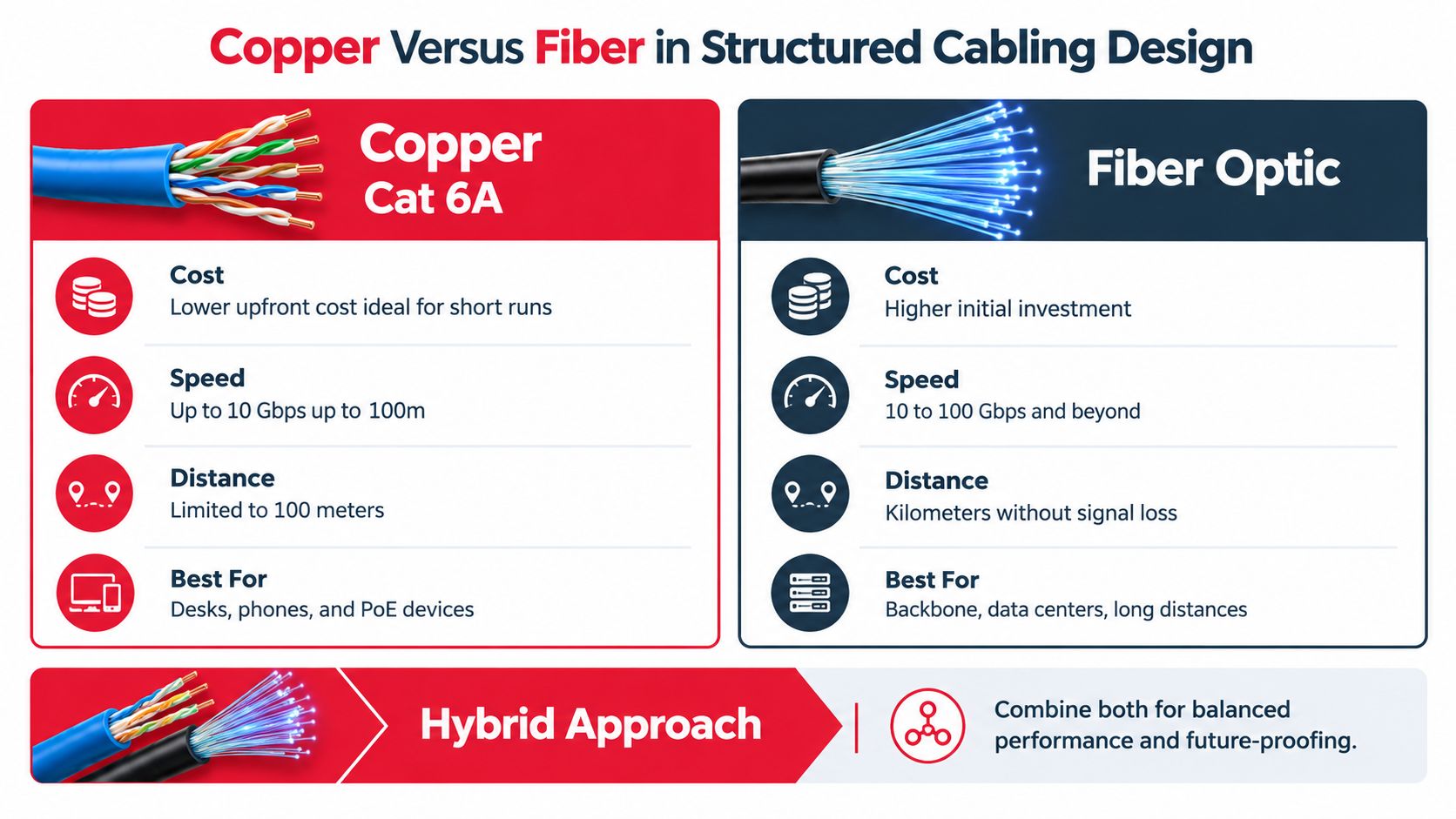
Copper remains the practical default for many horizontal runs to desks, phones, cameras, and wireless access points. It can support Ethernet to the edge and, just as important, it can deliver power over the same cabling path to many endpoint devices. That keeps edge deployment simple.
Copper is often the right fit when you need:
- Endpoint power: Phones, cameras, and access points often benefit from a single cabling path for connectivity and power.
- Short, repeatable runs: Office floors and standard device zones usually map well to structured copper layouts.
- Lower complexity at the edge: Technicians can terminate, patch, and replace common copper links quickly.
Where fiber becomes the better design choice
Fiber is usually the stronger option for backbone links, long runs, high-density data center environments, and sites that expect bandwidth growth without frequent recabling. It also avoids electromagnetic interference concerns that can complicate some environments.
A simple comparison helps:
| Design factor | Copper Cat 6A | Fiber optic |
|---|---|---|
| Distance | Best within structured copper channel limits | Better for longer backbone and interconnect paths |
| Power delivery | Can support powered edge devices | Requires separate power for endpoints |
| Interference | More sensitive in noisy or dense environments | Immune to electromagnetic interference |
| Upgrade posture | Strong for many edge deployments | Better for high-capacity backbone growth |
For readers comparing access technologies from the user side, this overview of choosing between DSL and fiber is a useful companion because it helps connect last-mile service decisions with what happens inside the building after the handoff.
A short explainer can help visualize the decision space:
Why more environments are shifting toward hybrid and fiber-centric layouts
Market direction matters here. One 2026 industry report says the global structured cabling market grew 21% in 2025 to $9.08 billion, adding $1.3 billion in a single year, while the data-center segment grew 54% and now accounts for more than two in five installations globally, up from 21% in 2015–2018, according to Data Centre Review's market coverage.
That doesn't mean copper is disappearing. It means planners are asking better questions. In a data center, physical space, density, thermal management, and long-term bandwidth all push design toward more fiber in the backbone and interconnect layers. In an office or campus, a hybrid design often lands in the sweet spot: fiber where reach and growth matter, copper where device power and low-cost edge connectivity still win.
A future-proof design isn't the one with the most fiber or the most copper. It's the one that assigns each medium to the part of the network where it creates the least rework later.
Design Principles for Reliable and Scalable Networks
Cabling quality shows up most clearly after the install crew leaves. If the design is sound, operations feel ordinary. Changes are controlled, outages are easier to isolate, and upgrades don't start with demolition.
Reliability starts with physical discipline
The first principle is pathway control. Cables need defined routes, separation from hazards, and protection from crush points, strain, and sharp bends. That sounds basic, but many long-term failures begin with a rushed pull through an overcrowded tray or an over-tightened bundle at the rack.
The second principle is traceability. Every cable should be identifiable at both ends, and that labeling should map back to documentation the operations team can use. A label without an as-built record helps less than people think.

Three design habits that prevent expensive rework
- Build spare path capacity: If trays, conduits, and rack managers are already full at turnover, the next project will cut corners. Leave room for growth so the network can absorb change cleanly.
- Use modular cross-connects: Patch panels and defined handoff points let teams reassign services without re-terminating installed cable.
- Document the install, not the planned one: Field conditions change. The final record needs to reflect what was built.
Here's where business outcomes connect directly to the physical layer. A network team may approve the right switch architecture and still inherit months of avoidable pain if cable pathways are undersized or labeling is inconsistent. The labor cost of repeated troubleshooting, after-hours tracing, and partial rebuilds often exceeds the savings from cutting corners during installation.
Scalability depends on decisions made early
Greenfield projects make this easier because teams can plan the room layout, pathway sizes, and backbone strategy before ceilings close and racks fill up. Retrofit projects require more judgment. You may need to preserve existing service while building cleaner cross-connects in parallel, then migrate area by area.
That work is where implementation partners matter. For example, Southern Tier Resources handles fiber-optic infrastructure deployment, splicing, testing, structured cabling, and as-built documentation across broadband and data center environments. That's relevant because scaling isn't just a design exercise. Someone still has to build, test, and hand over a plant that operations can maintain.
Documentation is part of the infrastructure. If the records are wrong, the cable plant is only half finished.
When teams treat reliability, scalability, and maintainability as one design problem instead of three separate tasks, they avoid the cycle where every upgrade creates a new patch of technical debt.
Real-World Use Cases Across Industries
The same structured cabling principles show up in very different environments. What changes is the consequence of getting them wrong.
Carrier and ISP fiber expansion
A telecom carrier building out broadband infrastructure doesn't stop needing structure just because the medium is fiber. At the hub, cabinet, or distribution point, organized routing, clear splice records, labeling discipline, and test documentation determine how quickly services can be activated and how cleanly faults can be isolated later.
In these environments, the cabling system isn't just serving one office floor. It's supporting customer turn-ups, maintenance dispatches, and expansion planning. If a distribution enclosure grows without consistent organization, each new activation gets slower and every trouble ticket gets more expensive to resolve.
Hyperscale and enterprise data center fit-outs
Data center projects raise the stakes. High-density racks, mixed media, airflow constraints, and aggressive uptime expectations leave very little room for sloppy routing or undocumented changes. Fiber trunk placement, patch field organization, vertical and horizontal management, and disciplined segregation of pathways all affect day-to-day operations.
This is also where the market is clearly shifting. Independent forecasts estimate the global structured cabling market at about $13.45 billion in 2026, with projected growth to $21.26 billion by 2031, while North America alone is projected at $8.76 billion in 2026. That same market view ties growth to hyperscale data center expansion, enterprise modernization, and higher bandwidth demand, according to Mordor Intelligence's structured cabling market analysis.
The practical implication is straightforward. More buyers aren't just asking whether they need structured cabling. They're asking whether a copper-first layout still makes sense, or whether a fiber-centric design better matches density, latency, and growth requirements.
Municipal and utility broadband projects
Municipalities and cooperatives face a different version of the same problem. They may start with a pilot area, a limited budget, and a near-term need to reach underserved locations. But if the foundational plant isn't documented and modular, expansion gets messy fast.
A well-structured deployment gives those teams options:
- Phased growth: New service areas can be added without rebuilding the original distribution logic.
- Cleaner maintenance: Field technicians can identify segments, handoffs, and records without relying on institutional memory.
- Better lifecycle planning: Decision-makers can see which parts of the plant are ready for growth and which need reinforcement.
The environment changes, but the rule doesn't. When cabling is organized, tested, and documented, the network can expand without losing its shape.
That's why structured cabling belongs in conversations about business continuity and infrastructure finance, not just in low-level installation checklists.
Installation and Documentation Best Practices
A structured cabling project is won or lost in field execution. Good drawings don't protect a cable that's been over-bent during a pull, and a clean rack photo doesn't prove the links were certified correctly.
What crews need to get right the first time
Start with careful handling. Pull cables with controlled tension, maintain bend radius, protect jackets, and avoid crushing bundles in trays or under hardware. For copper and fiber alike, terminations need the right tools, clean prep, and consistency from panel to outlet.
Then test what was installed. Visual checks aren't enough. Teams need proper certification for the medium and application, plus records tied back to labels and locations.
A useful reference point for buyers comparing provider capabilities is Amax IT network solutions, which shows the kind of installation scope many organizations evaluate when they need structured network work performed and documented professionally.
The paperwork is part of the deliverable
Every completed project should hand over more than working links. It should include:
- As-built plans: What was installed and where it was routed
- Label schedules: Panel, port, pathway, and endpoint naming records
- Test reports: Results matched to individual runs
- Asset records: Enough detail for future moves, audits, and troubleshooting
When those records are complete, the network stays operable long after the original crew is gone. That's the promise behind the answer to "what is structured cabling." It's not just orderly installation. It's a physical network that stays understandable for years.
Southern Tier Resources designs, builds, tests, and documents telecom infrastructure for carriers, broadband providers, enterprise environments, and hyperscale data centers. If you're planning a new cabling system, expanding a fiber footprint, or cleaning up a network that's become hard to operate, visit Southern Tier Resources to see how their engineering, construction, and maintenance services support reliable, scalable physical networks.