Telecom and MSO/CATV utilities represented 51% of all reported underground utility damage incidents in the Common Ground Alliance's 2025 DIRT data, which recorded 221,717 unique damage reports. The 2025 DIRT findings expose an uncomfortable field reality: underground cable protection fails more often through poor locating, weak coordination, and uncontrolled excavation than through inadequate burial depth alone.
A buried fiber route needs overlapping controls. Depth, conduit, direct-burial construction, warning tape, route markers, accurate records, qualified locators, potholing, and disciplined excavation each address a different failure mode. Remove one layer and the remaining controls must carry more risk.
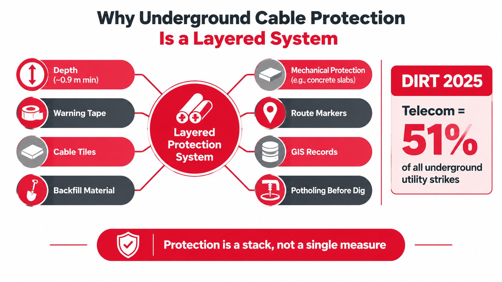
Why Underground Cable Protection Is a Layered System
Telecom and CATV accounted for 51% of all reported underground utility damage incidents in the 2025 DIRT data. The practical lesson is clear: cable protection cannot rest on cover depth alone. Depth helps separate a route from routine surface work, but it does not show an excavator where the cable runs, confirm that records are accurate, or account for a changed grade. A deeper cable with poor records can still be struck.
Protection works as a chain of controls. Depth, conduit or armor, warning tape, route markers, accurate records, qualified locating, potholing, and controlled excavation each address a different failure mode. If one layer is weak, the others carry more risk.
The same Common Ground Alliance DIRT data report identifies 30% of telecom and CATV damages as self-inflicted. The remaining incidents were mainly associated with other utility work. Coordination and locate quality are therefore part of the protection system itself, not paperwork.
Weight the layers by the actual failure risk
A design review should test what each control prevents:
- Depth reduces exposure to surface activity, but rock, frost, existing utilities, and changing grades can reduce that margin.
- Conduit or armor limits crushing, pulling, and impact exposure, while affecting replacement and repair access.
- Warning systems give future crews a physical warning before they reach the asset.
- Locate and records turn a buried route into usable field information.
- Excavation control keeps machinery out of an unverified tolerance area.
Budget usually produces more protection when it improves route records, locate response, potholing, and contractor briefings before adding marginal depth throughout the trench. For exposed copper, cabinets, and other vulnerable infrastructure, property protection against copper theft can address risks outside the trench.
Practical rule: Treat every buried route as a chain of controls. If one link is weak, strengthen locating, marking, and excavation procedures before relying on additional burial depth.
Choosing Installation Methods and Materials
Material selection starts with the route, not the cable catalogue. A ducted route gives the owner a protected pathway and a better chance of future replacement. Direct burial can reduce civil work, but the cable itself must carry more responsibility for crush resistance, moisture protection, and resistance to rough ground conditions.
For communications routes, project specifications commonly evaluate cover in the 24 to 36 inch range, while low-voltage power designs may use 24 inches where local rules permit. Medium-voltage work must follow the applicable electrical code and project requirements, including the relevant provisions of NEC Table 300.50. These values aren't universal permissions. The authority having jurisdiction, road owner, railroad, utility owner, and permit documents control the final requirement.
| Application | Min. Cover | Conduit | Warning Tape | Bedding/Rock Shield |
|---|---|---|---|---|
| Communications route | 24 to 36 in. by project rule | HDPE or PVC where replacement, crossings, or mechanical protection justify it | Place above the cable according to the approved trench detail | Sand or screened backfill in rocky or debris-filled soil |
| Low-voltage power | 24 in. where permitted by the governing design | Use where separation, protection, or future access matters | Use the approved electrical warning system | Add a shield or engineered bedding where sharp material remains |
| Medium-voltage power | Per NEC Table 300.50 and local requirements | Frequently selected for controlled pathways and crossings | Follow utility and electrical specifications | Engineer the section for fault, impact, and soil conditions |
| Road or railroad crossing | Project and owner requirement | Sleeve or encasement is often justified | Make the route conspicuous for future work | Concrete cap or flowable fill may be required |
| Rural direct-burial fiber | Route-specific | Omit only when the cable construction and soil support it | Detectable tape and tracer provisions should be evaluated | Use armor, rock shield, or selected bedding where needed |
Match the cable construction to the route
HDPE conduit earns its cost when future cable replacement, additional capacity, or difficult access matters. PVC Schedule 40 can work well in rigid, accessible sections, but crews need to respect joint alignment, bend limits, and pull tension. A four-inch sleeve through pavement may look oversized during construction. It can pay for itself when a damaged cable needs replacement without cutting the pavement again.
Direct-burial figure-eight cable or armored fiber is reasonable on a route with suitable soil, predictable access, and no clear need for future pulling. It isn't a substitute for route verification. Armor protects the cable from selected mechanical threats, but it won't tell a backhoe operator where the line is.
Use detectable warning tape above the cable, with the exact offset defined by the civil detail. Canadian electrical safety guidance specifies continuous red or yellow marker tape marked “danger buried cable,” placed about halfway between the cable or duct and grade, covering the installation width, with multiple tapes spaced up to 600 mm apart. It also permits permanent above-ground markers at intervals of no more than 15 m or at each direction change. The Electrical Safety Authority bulletin is a useful benchmark for turning a warning concept into an installable detail.
Where backfill contains stone, demolition debris, or sharp fragments, use screened material, sand bedding, rock shield, or an engineered protective layer. In wet ground, specify a cable construction suited to water exposure, such as gel-filled or dry-core OSP cable with suitable water-blocking components. The choice should follow the route's moisture, rodent, pulling, and maintenance conditions, not a generic preference.
For short protected transitions around equipment, understanding flexible metal conduit types helps the designer avoid specifying a rigid solution where movement, vibration, or tight routing requires flexibility.
Verifying Cable Location Before Any Excavation
A locate ticket is an authorization to begin a process, not proof that the cable has been found. Records may be incomplete, paint may be displaced, and an old route may not match the grade shown on the drawing. The safe sequence moves from documentary evidence to non-destructive confirmation, then to machine work.
Use a verification sequence that crews can repeat
Pull records first. Review as-builts, GIS data, permit drawings, splice diagrams, and previous locate notes. Mark uncertainty on the work plan instead of presenting an approximate route as fact.
Request the one-call locate. Submit the ticket for the precise white-lined work area, confirm that every operator has responded, and check the ticket status before mobilization. Private utilities and owner-installed facilities may require separate locating.
Sweep the route. Use electromagnetic detection and ground-penetrating radar where conditions support it. Try more than one frequency and compare the instrument response with the records. A single sweep can miss a nonmetallic duct, a weak tracer, or a congested crossing.
Pothole the conflicts. Use vacuum excavation or hand tools at crossings, tie-ins, and other high-consequence points. The Hong Kong utility safety method recommends obtaining service records, appointing a competent detector, marking the surface, verifying with hand-dug trial pits, exposing utilities with hand tools near the asset, and supporting exposed services with warning notices. The Highways Department safety notice reflects the correct order of operations.
Expose laterally before trenching or boring. Confirm the route's horizontal position and actual depth, then establish a no-machine zone around the exposed asset. Only after that should the crew proceed with mechanical excavation or a bore plan.
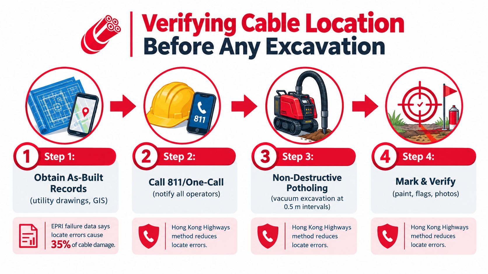
EPRI underground distribution data places the majority of underground cable-system failure rates between 0.7 and 2 failures per 100 miles per year. EPRI's underground failure data shows why owners should treat verification as an operating control rather than a one-time construction form.
Potholing is the only step in this sequence that physically confirms the cable's position and depth. Within the tolerance area, an air lance, bucket, or backhoe tooth can turn an uncertainty into a cut in seconds.
No ticket clearance, no tooth on the bucket.
Warning Tape, Color Codes, and Surface Markers
Warning systems work in layers because each one serves a different person. Buried tape warns the excavator who has already reached the upper trench. Surface paint guides the locator and operator before digging. Permanent markers help maintenance crews find the route years later, after paint, memory, and temporary stakes have disappeared.
The American Public Works Association color code assigns red to electric power cables and orange to communications, alarm, or signal lines. Those colors are widely used across North American utility locating, but local requirements can add conventions or modify marking practice. Call the applicable state one-call center and check the owner's standards before treating a color code as universal.
| Color | Utility Type | Typical Protection |
|---|---|---|
| Red | Electric power | Use with electrical warning tape, route markers, and approved separation |
| Orange | Communications, alarm, or signal | Pair with detectable tape, tracer provisions, and accurate route records |
| Yellow | Gas or other owner-designated service | Follow the local utility marking specification |
| Blue | Potable water | Protect against excavation and maintain clear crossing records |
| Purple | Reclaimed water | Follow the water owner's marking and separation rules |
Build a marking system that survives the project
Standard polyethylene tape can provide a visible warning, but it may not respond to a locator. Foil-backed detectable tape adds a conductive target that a compatible locating instrument can detect. Tracer wire or tracer balls can be a stronger choice on long horizontal directional drilling pulls, especially where the installed cable or duct itself won't provide a reliable locating signal.
Place permanent markers at bends, splices, crossings, changes in direction, and other points where a future crew needs a fixed reference. Canadian guidance permits above-ground markers at intervals no greater than 15 m or at every direction change, which provides a practical benchmark for conspicuous route identification. Use legible labels, durable posts, curb stamps, or tracer-ball risers suited to the site.
A marker that fades, breaks, or loses its relationship to the route has little value. Photograph each marker before backfill and after final restoration, record its coordinates in GIS, and include the marker ID in the splice and route documentation. The next locator may be a different contractor, and the next excavation may occur after several winters, repaving, landscaping changes, or staff turnover.
Right-of-Way Coordination and Damage Prevention
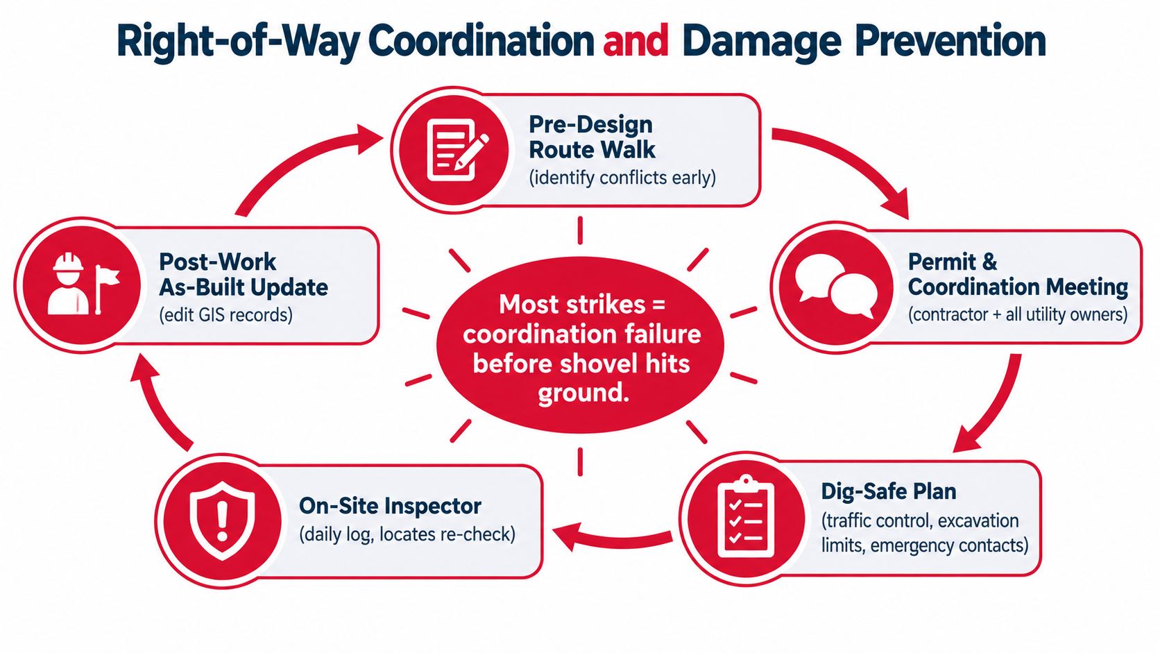
Many strikes are decided before the shovel reaches the soil. A route that crosses a railroad, municipal pavement, private easement, or another utility corridor needs a coordination record that makes responsibilities visible to every party.
Start with a pre-design route walk. Invite the municipality, railroad representative, easement holder, utility owners, designer, and construction lead. Walk the proposed alignment, identify crossings and access constraints, and build a utility conflict matrix that names the owner, facility type, locate responsibility, protection requirement, and decision deadline.
Put controls on the mobilization calendar
- Define the dig zone: White-line the exact work area before submitting the one-call request, then verify that the ticket covers all planned trenching, potholing, staging, and bore paths.
- Bring the right people together: Hold a pre-excavation meeting with the contractor, locator, subcontractors, inspector, and affected utility owners.
- Reconfirm daily: A tailboard briefing should review marks, tolerance limits, crossings, emergency contacts, and the equipment sequence before movement.
- Qualify the locate work: Use a competent locator who can interpret records, electromagnetic response, radar limitations, and congested utility corridors.
- Close the record: Return redlines, GPS points, photos, depth observations, splice information, and marker locations to the GIS team after installation and backfill.
A practical construction packet should contain the ticket, responses, locate sketches, photographs of paint and flags, pothole logs, daily briefings, inspection notes, and approved changes. If a neighboring crew damages the line later, that record helps the owner show what was marked, what was verified, who received the briefing, and where the facility was documented.
Organizations evaluating route design, construction support, and infrastructure documentation can also review the capabilities described by Southern Tier Resources, including underground fiber construction, testing, and as-built documentation.
Maintenance Planning After the Trench Closes
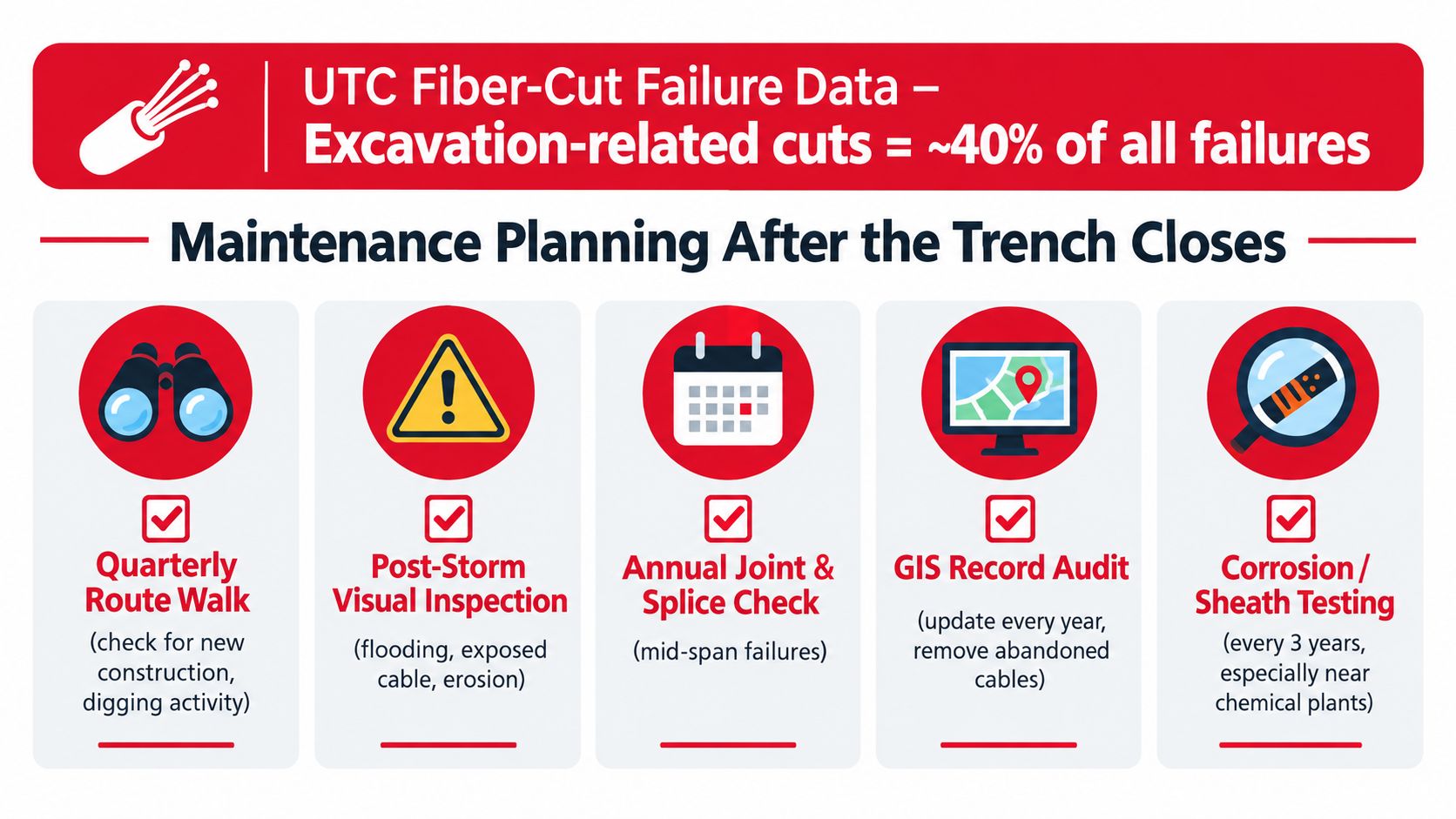
Closing the trench ends installation, not the protection program. A Hong Kong Highways Department practice guide citing UTC data attributes 40% of fiber cuts to excavation, 22% to human error, 20% to rodents, 14% to right-of-way clearing, and 4% to other causes. The UTC underground fiber report) therefore points maintenance toward route conditions and the people working nearby, not just the cable jacket.
Turn failure causes into field actions
Excavation exposure requires route surveillance. Walk active construction corridors during the construction season, patrol the wider route during the rest of the year, and inspect after storms for erosion, exposed cable, washouts, or new third-party work. Revise the locate packet when site conditions change.
Human error requires disciplined installation and repair. Establish an OTDR baseline after acceptance, compare later traces against it, verify splice closures, maintain bend-radius limits, and investigate every abnormal result before returning the span to service. A splice diagram helps only when it is tied to the route record.
Rodent damage calls for local treatment. Use armored cable, hardened conduit, or an approved deterrent in known chew zones. Greater burial depth does not address an animal reaching the route from the side.
Moisture and environmental exposure need separate checks. Test manhole pumps, inspect sumps and entry points, check seals and gaskets, and look for sheath damage or water migration. Assign route walks, post-storm inspections, splice and joint reviews, GIS audits, and targeted sheath testing to named personnel on a practical schedule.
A Hong Kong Highways Department practice guide citing UTC data reports that 68% of utilities reported no fiber failures during the previous 12 months, while more than 25% reported attenuation problems. The maintenance response should balance third-party excavation controls with optical testing, closure inspections, bend control, and accurate documentation.
Field Checklist and Common Questions
A crew leader should be able to sign off the work without searching through a design package. The checklist below condenses the layered model into actions that belong in the field packet.
Before work starts
- Locate status: Confirm the one-call ticket, utility responses, private locates, and ticket expiration.
- Route evidence: Compare GIS, as-builts, paint, flags, and pothole results.
- Depth verification: Record actual exposed depths at crossings and tie-ins.
- Crew briefing: Review tolerance limits, hand-dig requirements, emergency contacts, and the equipment plan.
During excavation
- Protect the exposure: Support exposed utilities and keep warning notices visible.
- Control the machine: Keep mechanical equipment outside the verified exclusion zone.
- Watch the route: Stop when marks, soil conditions, drawings, or observed utilities don't agree.
- Preserve the record: Photograph crossings, conduit condition, cable position, and marker placement.
After backfill
- Inspect the installation: Confirm conduit integrity, bedding, warning tape, cover, and restoration.
- Update records: Submit GPS points, depths, splice diagrams, redlines, photos, and marker IDs.
- Close the ticket: Retain the locate responses and final construction sign-off with the project file.
Questions that create liability
Who pays when an unmarked utility is struck? Responsibility depends on jurisdiction, ownership, contracts, ticket obligations, negligence, and the facts of the incident. Don't assume an unmarked facility automatically eliminates exposure. Preserve the locate ticket, correspondence, photographs, GPS logs, pothole records, and daily briefings.
How often should a buried line be relocated? Re-locate it whenever new excavation, grading, boring, utility work, or route uncertainty affects the work area. A previous ticket doesn't protect a new scope of work.
Does depth alone prevent damage? No. Depth reduces some mechanical exposure, but accurate locating, physical verification, clear marks, and controlled excavation usually determine whether a crew finds and protects the cable.
What records matter years later? Keep the complete chain from design and permit through locate, exposure, installation, testing, restoration, and GIS update. A record that field crews can't retrieve quickly is not a dependable protection layer.
Southern Tier Resources provides engineering, underground fiber construction, directional boring, fiber placement, splicing, testing, and detailed as-built documentation for telecom and broadband infrastructure. To strengthen your next route from design through maintenance, visit Southern Tier Resources and discuss the locate, coordination, and construction controls your project requires.