The capstan is turning, the reel is paying out, and everyone on the crew is watching the tension monitor. Then a junior technician points to two numbers on the paperwork: a cable's 2,700 N maximum pull tension and a fiber data sheet showing 100 kpsi proof testing. Which number controls the pull?
That question exposes the central problem with a fiber tensile test. Laboratory results describe the behavior of a specimen or fiber population under a defined method. Field crews must turn those results into decisions about pulling equipment, route length, bend handling, cable construction, and residual strain. The numbers matter, but only when you understand what each one measures.
A Day on the Crew When the Cable Spec Sheet Matters
The foreman kneels beside a reel of loose-tube cable while the capstan hums. The route runs through a long conduit section, and the pull plan leaves little room for improvisation. A junior technician holds the cable certificate and asks why the document lists a 2,700 N rated pull tension, while the fiber inside the cable is identified as proof-tested at 100 kpsi.
The foreman's first answer is simple: those figures describe different parts of the system. The proof-test value belongs to the glass fiber and indicates that the fiber passed a controlled tensile screen before shipment. The cable rating belongs to the finished assembly, including the strength members, buffer tubes, binders, jacket, pulling eye, and the way those components transfer load.
A crew shouldn't set the capstan from the fiber proof-test figure. The cable manufacturer's rated load, installation instructions, pulling-eye rating, route design, and project specification govern the immediate operation. The fiber result still matters because it helps explain the strain margin built into the cable design and the consequences of mishandling the cable during installation.
Follow the load path
Ask these questions before the pull begins:
- What is being loaded? Is the force carried by the cable's central strength member, aramid reinforcement, armor, pulling eye, or some combination?
- Which load limit applies? A short-term installation limit is different from a sustained service load.
- Where is the tension measured? A capstan display, dynamometer, pulling-eye load cell, and cable entry point may not show identical conditions.
- What does the route add? Bend friction, sidewall pressure, lubricant behavior, conduit condition, and intermediate access points all affect the required force.
A pull rope may be appropriate for one route, while a pre-laced innerduct or intermediate assist point may be safer for another. The right decision depends on the cable's approved method and the calculated installation tension, not on a bare-fiber strength number copied from a laboratory certificate.
Practical rule: Treat the proof-test result as evidence about the fiber's screened reliability. Treat the cable's rated tensile load as the operating limit for the installed product.
The foreman can now answer the technician's question without dismissing either number. The 100 kpsi proof-test value helps define the quality of the glass. The 2,700 N cable rating determines how the crew manages today's pull. Confusing those roles can turn a compliant cable into a damaged link before the first splice is made.
What a Fiber Tensile Test Actually Measures
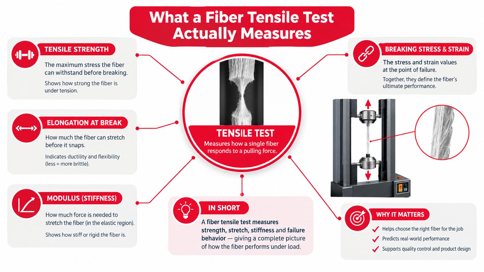
A fiber tensile test applies a uniaxial tensile load to a specimen and records how the specimen responds as the load increases. For bare optical fiber, the technician is evaluating glass, not the complete cable assembly. The test produces a force and elongation record, which engineers convert into stress and strain.
Strain describes proportional elongation:
- Strain = change in length divided by original length
- Stress = applied force divided by fiber cross-sectional area
A long, thin bungee can stretch noticeably under a modest load. Glass fiber behaves differently. It has high stiffness and very limited tolerance for a critical surface flaw, so it can break after relatively little elongation even when the visual defect is too small to see during ordinary handling.
Read the curve, not just the peak
The load or stress versus elongation curve supplies several useful results:
- Breaking strength is the stress at fracture.
- Elongation at break shows how much the specimen extended before failure.
- Young's modulus is the slope of the linear elastic portion, which represents stiffness.
- Fracture location helps reveal whether the result represents the specimen or a mounting defect.
Silica fiber has a modulus of approximately 70 GPa, but that figure doesn't mean every fiber will break at the same stress. Glass strength is statistical. Tiny flaws vary from specimen to specimen, and longer gauge lengths expose more opportunities for a critical flaw to occur.
That's why laboratories use strength distributions rather than relying on one “typical” break value. A Weibull analysis helps describe the probability of failure across a population and shows how the weakest portion differs from the central portion. A design engineer needs that distribution because field reliability depends heavily on the low-strength tail.
Why geometry control matters
The result is sensitive to the measured cross-sectional area. ASTM C1557 calculates tensile strength from peak force divided by the fiber area near the fracture location, while Young's modulus comes from the linear stress-strain region. The ASTM C1557 method description shows why diameter measurement, specimen alignment, mounting, and fracture-location inspection directly affect the reported value.
A test number without its gauge length, strain rate, specimen preparation, and failure mode is incomplete. Before comparing two certificates, confirm that they describe the same kind of specimen and test.
How Proof Testing Screens Weak Fibers Before Shipment
Production proof testing serves a different purpose from destructive sample testing. A manufacturer subjects 100% of fibers to a short-duration tensile strain of about 1%, roughly 0.69 GPa or 100 kpsi, to eliminate the lowest-strength flaw population before shipment, as described in Prysmian's fiber lifetime technical document.
The process is a reliability filter. Fibers that survive the proof load have had critical extrinsic defects screened out, so the residual strength distribution shifts upward. The test doesn't prove that a finished cable can be pulled at the same stress, and it doesn't replace cable-level qualification. It establishes that the shipped fiber population has passed a defined minimum screen.
A weak surface flaw can dominate early-life failure. Proof testing removes that weak tail before the fiber enters the cable or network. This is especially important in long-haul and access deployments, where a latent defect may grow under repeated service stress, handling, environmental exposure, or an installation event that leaves residual strain.
Interpret the strain level carefully
The verified industry description supports an approximately 1% proof-test strain for optical fiber. It doesn't support treating every other proof-test value as a universal field rating. A lower or higher screening condition may apply to a particular product, fiber design, or manufacturing specification, and the certificate must identify the actual requirement.
| Proof-Test Strain | Screen Stress, approximate | Typical Application | Field Implication |
|---|---|---|---|
| Lower specified strain | Product-dependent | Fiber or cable specification | Use the manufacturer's stated acceptance and installation limits |
| About 1% | About 0.69 GPa, or 100 kpsi | Industry optical-fiber proof screening | Confirms removal of the lowest-strength flaw population, not a cable pull setting |
| Higher specified strain | Product-dependent | Specialized qualification or customer requirement | May increase the screened strength floor, but can affect manufacturing yield |
The practical effect is cause and effect, not a marketing label. A fiber that breaks during the proof load is removed from the shipment. A fiber that survives has demonstrated resistance to that screening condition, but the finished cable still needs protection from excessive pulling force, sharp bends, compression, and residual strain.
Keep the service question separate
A proof test asks, “Did this fiber survive the defined screen?” A field plan asks, “What force and handling conditions will this cable experience during installation and service?” Those questions are related, but they aren't interchangeable.
Crews should record the proof-test requirement as part of quality documentation, then use the cable manufacturer's rated tension and approved installation procedure to control the pull. That separation prevents a common error, using a material-screen value as though it were an operating limit.
Key Standards That Govern Fiber Tensile Testing
A specification package can contain several standards because each document governs a different layer of the decision. ASTM C1557 covers single-fiber tensile testing for ceramic, glass, carbon, and other fibers. It defines how the specimen is evaluated, how force and cross-sectional area are handled, and how stress, modulus, and fracture behavior are reported.
Optical-fiber methods answer questions about the fiber itself, including proof-test verification. IEC 60793-1-30 provides a concrete reference for optical-fiber proof testing. Cable standards address the finished assembly, including how fiber, coatings, and strength members perform during handling and installation. ICEA S-87-640 is a document crews can request when reviewing mechanical performance requirements for fiber-optic cable.
Match the document to the decision
| Standard or document | Scope | Key parameter | Applies to |
|---|---|---|---|
| ASTM C1557 | Single-fiber tensile testing | Peak force, cross-sectional area, stress, and modulus | Bare glass and other individual fibers |
| IEC 60793-1-30 | Optical-fiber proof-test method | Defined proof-test load and fiber response | Optical fiber |
| ICEA S-87-640 | Cable mechanical performance | Rated installation and service loads | Fiber-optic cable assemblies |
| Project specification | Contract acceptance and installation requirements | Approved limits, records, and test evidence | The specific deployment |
Use ASTM C1557 when reviewing a laboratory report about intrinsic fiber strength. Use the optical-fiber method when checking proof-test requirements. Use the cable standard and manufacturer's data when deciding whether a reel is suitable for a planned route. A bare-fiber tensile value does not set the allowable pull for a completed cable.
A cable certificate should identify the product, lot, test method, and acceptance criteria. If a reel arrives without adequate documentation, do not substitute habit or a generic internet value. Hold it for engineering or quality review, compare it with the approved submittal, and request the manufacturer's certificate or technical clarification.
Standards can overlap while controlling different decisions. A bare-fiber result may support material qualification under IEC 60793, while the cable pull rating under ICEA S-87-640 addresses the finished assembly. Installation acceptance then requires tension records and an OTDR baseline. The documents work together because each one answers a defined question.
The following video can help junior personnel visualize tensile-testing equipment and specimen behavior before they review field records.
Equipment, Specimens, and Test Parameters in Practice
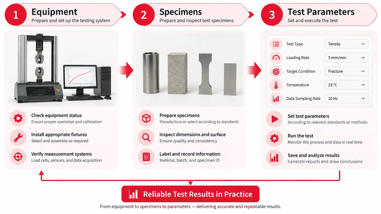
Every tensile value on a certificate comes from a physical setup. The machine must apply force smoothly, measure it accurately, and hold the specimen without creating an artificial break at the grip. A laboratory may use capstan-style fixtures or face grips, depending on the fiber and method, to distribute load and reduce stress concentration.
Technicians also control the environment. Temperature and humidity can affect coatings, interfaces, and test repeatability, so conditioned runs require documented chamber settings and specimen equilibration. The test record should identify the machine, calibration status, fixture arrangement, environmental condition, gauge length, strain rate, and failure location.
Prepare the specimen without adding damage
Bare glass preparation demands discipline:
- Strip the coating carefully. A nick or scratch introduced during stripping can become the failure origin.
- Clean the gauge section. Residue can interfere with measurement or create an unintended stress concentration.
- Mount the fiber in alignment. Eccentric loading can distort the result.
- Inspect the fracture location. A break at the grip often indicates a fixture or preparation problem rather than representative fiber strength.
Gauge length changes what the test samples. A short screening length may miss flaws that appear across a longer population. A longer design gauge can provide a more representative view of distributed defects, but it also demands better handling and alignment.
Control the rate and analyze the population
ASTM C1557 defines a strain-rate condition around 2.5% per minute, while optical-fiber protocols may use other controlled rates. The ASTM C1557 information reinforces the need to compare like with like. A faster pull can produce a different apparent strength because the specimen has less time for time-dependent crack growth and environmental effects to influence failure.
The laboratory then evaluates more than the average break. It reviews scatter, fracture locations, outliers, and the strength distribution. A clean report explains whether the result represents intrinsic material behavior, surface condition, coating interaction, or a setup problem.
A tensile number is only as useful as the method behind it. Without specimen history and test conditions, comparison becomes guesswork.
Translating Lab Results Into Field Decisions
A crew is preparing a make-ready replacement when the cable datasheet shows several tensile values. The immediate question is not, “What is the tensile strength?” Ask instead which failure mode was measured, over what gauge length, and for which deployment condition. Corning's technical discussion of optical-fiber tensile testing helps separate controlled laboratory results from decisions about pull tension, bend handling, and residual strain.
A bare-fiber proof result describes the screened glass population. A cable pull rating describes the finished cable during installation. Use the cable rating to set equipment and control the route. Use the fiber result to understand why handling damage matters and why a small surface flaw can reduce the available strain margin.
Build the pull plan around the cable
For a conduit pull, calculate or verify expected tension from route geometry, cable weight, bend configuration, friction assumptions, lubricant compatibility, and the installation method. Compare that result with the cable's approved maximum installation tension. Set the capstan limit below the approved limit, and define the response if tension rises unexpectedly.
A pull that looks acceptable on a straight section can become excessive at a bend. Sidewall pressure, a tight handhole entry, or an unsupported transition can impose local strain even when the displayed pulling tension remains within the set limit. Check guides, sheaves, entries, and storage loops as parts of the same mechanical path.
Aerial work has a different load pattern. The crew must account for sag, span geometry, support hardware, wind exposure, and the cable's long-term service condition. A cable may tolerate a brief installation event yet lack sufficient margin for sustained tension, aging, or environmental loading.
Use the manufacturer's limits as the control layer
| Lab or product parameter | What it tells you | Field use |
|---|---|---|
| Fiber proof-test condition | The screening condition passed by the fiber population | Quality and reliability evidence |
| Cable rated installation load | The approved short-term handling limit for the finished cable | Capstan and pulling-plan control |
| Cable service-load requirement | The condition allowed during operation | Aerial and long-term design review |
| Bend-radius requirement | The permitted curvature for the cable construction | Sheave, guide, entry, and storage setup |
Acceptance criteria change with the decision being made. A short-term installation load controls the pull, while a long-term service-load requirement controls the installed design. For a make-ready aerial replacement, the installer needs the cable's rated installation load and lashing-tension limit, not the fiber's proof value alone. For a conduit pull, the route calculation and cable limit determine whether the planned operation can proceed.
If calculated pull exceeds the approved cable limit, change the operation. Add an assist point, revise the route, improve lubrication, use an approved installation method, or stop for engineering review. Never convert a fiber proof-test value into a higher cable pull allowance. The proof number supports quality interpretation. The cable rating sets the field limit.
Safety, QA, and Reporting for Field Crews
A tensile number can support an acceptance decision only when the crew preserves the evidence around it. That starts with safe handling. Cleaved fiber scraps belong in a rigid, labeled disposal container, not loose in a pocket, truck bed, or work area. Everyone handling stripped or cleaved fiber should know where the container is and how to close it.
Laser-light precautions apply during OTDR and source testing. Never look into a connector or fiber end, and control access around active test equipment. Pulling operations add another hazard because stored mechanical energy can release suddenly if a pulling eye, rope, swivel, or attachment fails.
Record the installation as it happened
A defensible QA package usually includes:
- Reel identity: Record the reel number, cable product, lot information, and planned route.
- Certificate review: Match the manufacturer's documentation to the approved submittal and cable construction.
- Equipment status: Record the calibration or verification status of tension monitors and optical test instruments.
- Pull evidence: Preserve tension readings, route notes, lubrication details, and any stops or changes.
- Bend compliance: Photograph guides, sheaves, entries, and storage loops where the required bend-radius condition is visible.
- Optical baseline: Archive pre-pull and post-pull OTDR traces with instrument settings and test direction.
A post-pull trace doesn't replace mechanical records. It complements them. A clean optical result may show that the link passed the immediate test, but the installation record demonstrates whether the crew followed the approved mechanical plan.
Protect sample chain of custody
If a damaged or suspect fiber sample goes to a laboratory, label it with the reel, location, date, handling history, and person who collected it. Seal the sample so the receiving technician can identify whether the fracture occurred during installation, collection, packaging, or laboratory preparation.
Audit-ready habit: Write down the deviation when it occurs, not after the crew has moved on to the next section.
Any departure from the approved tension limit, bend condition, route, lubricant, or hardware should be escalated before the link is energized or accepted. The supervisor's job isn't to make an undocumented exception look normal. It's to preserve the facts so engineering and the owner can make an informed decision.
A Field Checklist Before the Next Pull
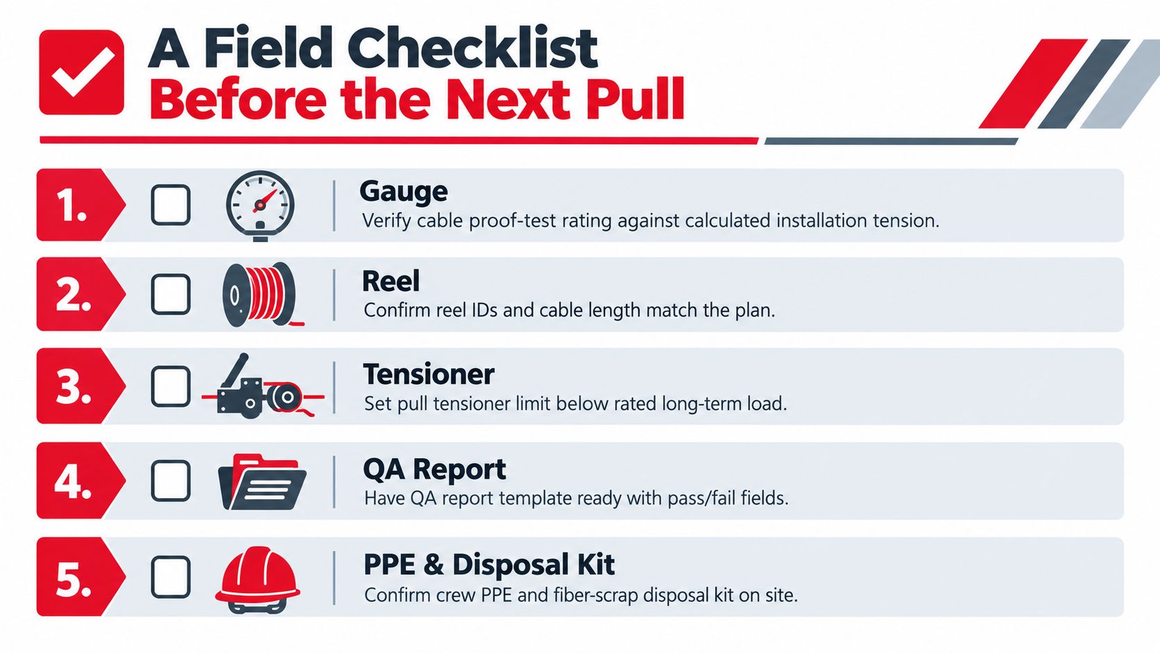
A supervisor can prevent most avoidable tensile problems by treating the pre-pull review as a decision gate. The team should be able to show how the route, cable, equipment, and records fit together before the reel moves.
Verify the mechanical plan
- Confirm the cable limit: Compare the approved maximum installation tension with the calculated route tension and the tensioner setting.
- Check bend control: Confirm that guides, sheaves, corner rollers, handhole entries, and storage arrangements support the cable's specified bend condition.
- Inspect the pulling path: Look for obstructions, damaged conduit, sharp edges, flooded sections, and transitions that could increase resistance.
- Review the pulling hardware: Verify pulling-eye, swivel, rope, and attachment compatibility with the approved installation method.
- Validate lubricant use: Confirm that the lubricant is compatible with the cable jacket and suitable for the conduit environment.
The crew should stage the tension monitor where the supervisor can see or receive readings during the operation. Establish a clear stop signal before the pull starts. Communication should cover the reel, capstan, intermediate points, and receiving end, with one person authorized to stop the operation.
Capture the evidence before and after
Take a pre-pull OTDR baseline and confirm that the trace is labeled to the correct reel and route. Record reel orientation, cable markings, starting length, equipment identification, and the names of the responsible crew members. If the route changes, stop and revise the plan rather than relying on memory.
During the pull, record unusual tension spikes, pauses, lubricant additions, rope changes, and any contact with guides or structures. After placement, inspect the cable at entries, bends, supports, and slack-storage points. Then complete the required OTDR, insertion-loss, continuity, and visual inspections under the project acceptance procedure.
Use a firm escalation rule
Stop the pull if the tension monitor approaches the approved limit, the cable loses control at a bend, the pulling hardware behaves unexpectedly, communication fails, or the route no longer matches the plan. Stop as well when documentation is missing and the crew can't verify the cable's identity or mechanical requirements.
A fiber tensile test provides valuable evidence, but it doesn't authorize improvisation in the field. The safe decision is to hold, document the condition, and obtain engineering direction before continuing.
Southern Tier Resources provides end-to-end telecom infrastructure support, including fiber deployment, make-ready construction, splicing, testing, and documentation. Visit Southern Tier Resources to connect with a safety-focused partner for disciplined cable installation and reliable network delivery.