The cabinet fits on the drawing, but the installer can't open its rear door once the cable tray is in place. Fiber shelves fill the available rack space, yet there's nowhere to store slack without tightening a bend. Then someone asks where the cabinet's bonding conductor should terminate.
These aren't cabinet-shopping problems. They're building-infrastructure problems that should be resolved before procurement. A structured cabling enclosure needs enough room for connections, safe working access, deliberate bonding, and documentation that still makes sense after the next network upgrade.
What a Structured Cabling Enclosure Does
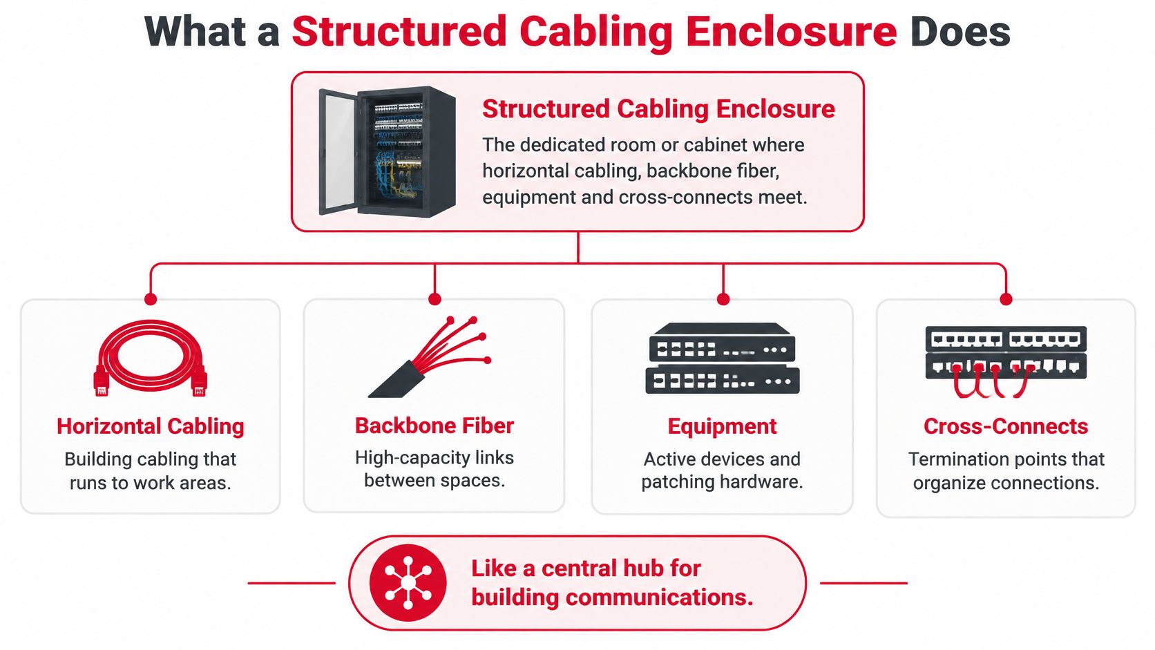
A structured cabling enclosure is the dedicated room or cabinet where horizontal cabling, backbone fiber, equipment, and cross-connects meet. It works like a junction point in a plumbing system: separate runs converge at one accessible place so technicians can isolate, connect, and repair them without dismantling everything nearby.
The terminology causes real confusion on projects. A cabinet is a physical product with a part number; a telecommunications room is a building space with walls, power, and clearances. A spec sheet that lists a cabinet size describes a product, while a floor plan that shows a telecommunications room describes allocated space. Treating the two as interchangeable is how working clearances disappear late in construction.
Where these spaces sit is set by the applicable TIA pathways-and-spaces requirements and the project design: telecommunications rooms and distributor spaces are located so backbone and horizontal pathways stay within their cabling-distance limits, with room left for access and growth. Location is a design decision shaped by pathway lengths and service clearances, decided before procurement rather than after.
The diagram below shows how the enclosure connects the building's communications infrastructure.
The interfaces that need coordination
An enclosure joins several physical systems:
- Pathways: Trays, conduit, sleeves, and cable supports bring services into and out of the space.
- Spaces: Rooms, racks, and cabinets provide mounting positions, working access, and environmental protection.
- Cabling: Copper, fiber, and patch cords connect equipment through terminations and cross-connects.
Teams newer to how horizontal and backbone cabling fit together can review the structured wiring guide for IT teams before planning the enclosure itself.
Each group asks something different of that convergence point. Carriers and ISPs need technicians to isolate a circuit without disturbing adjacent services. Data center operators need dense connectivity that remains reachable. Enterprise teams need moves and changes that avoid tracing unidentified cords through a crowded cabinet.
Design principle: Specify the enclosure as a serviceable connection point inside the building's bonding, clearance, and compliance system. A cabinet that merely holds networking equipment misses that purpose.
A sound design accounts for enclosure type, usable internal space, external working clearances, bonding connections, and acceptance records together. A larger cabinet alone cannot correct an inaccessible location or an undocumented grounding arrangement.
Enclosure Types and How to Choose Between Them
| Enclosure type | Typical size | Best fit | Main limitation |
|---|---|---|---|
| Wall-mounted cabinet | Compact wall footprint; depth set by equipment and cable exits | Small offices and light copper closets | Tight rear access and limited slack space |
| Floor-standing rack cabinet | Full-height format; width and depth selected around equipment and managers | Telecom rooms and data centers with mixed copper and fiber | Needs floor space and front clearance |
| Open-frame equipment rack | Rack-height frame with an open service envelope | Patch-heavy areas needing easy access | No dust, climate, or security protection |
| Fiber distribution enclosure | Rack-unit height selected by tray and cassette configuration | Fiber termination, splicing, and cross-connects | Fixed capacity; expansion needs planned trays |
| Outdoor pedestal or cabinet | Manufacturer-specific footprint and service envelope | Street-side broadband and wireless feeds | Needs suitable environmental protection and thermal control |
These are reference formats, not purchasing dimensions. Confirm overall dimensions, mounting positions, and service envelopes against the manufacturer's dimensioned drawing.
Match the format to the site
Start with connection media. A small office floor with light copper cabling may suit a wall-mounted cabinet, provided the patch cords and cable entries remain accessible. A carrier hub with trunk fiber, splice trays, and cross-connect shelves generally needs a floor-standing arrangement with deliberate rear access.
Next, consider growth. A cabinet that accepts today's patch panels may not accept tomorrow's deeper fiber shelf. Compare the proposed module's depth, cable exit direction, and mounting arrangement, not just its front-panel footprint.
The environment can change the choice completely. An open-frame rack works inside a controlled, secured telecommunications room, but it doesn't provide its own protection against dust, moisture, or unauthorized contact. For outdoor installations, the E & I Sales NEMA guide helps distinguish enclosure protection categories before selecting the appropriate rating for the site.
Access matters just as much as capacity. A wall cabinet can look economical until rear cable entries force technicians to work around tight corners. Swing-out construction may help, but only if the loaded cabinet can move without pulling its incoming cables.
Finally, check the available structure and space. Confirm wall support for mounted equipment, floor loading for populated cabinets, and an unobstructed route for installation and replacement.
Before choosing a type, record:
- Connections: Media, termination format, and cable-entry direction.
- Expansion: Planned modules and their service requirements.
- Environment: Indoor conditioning, moisture, dust, and exposure.
- Access: Front-only work or front-and-rear servicing.
- Space: Mounting support, footprint, and replacement route.
The right enclosure is the one technicians can operate safely throughout its service life, not necessarily the smallest available model.
Sizing for Clearance, Density and Growth
An enclosure can meet its own dimensional spec and still fail in service because the space around it was never sized with it. Clearance standards treat the cabinet, the pathways feeding it, and the working space beside it as a single system, so start from the room benchmarks before checking any cabinet datasheet.
| Requirement | Minimum or target value | Source basis |
|---|---|---|
| Unobstructed clear height | 2.4 m (8 ft) minimum | ANSI/TIA-569 pathways and spaces guidance |
| Finished floor-to-ceiling height | About 3 m (10 ft) recommended | Same ANSI/TIA-569 guidance |
| Front equipment clearance | 1 m (3 ft) minimum; 1.2 m (4 ft) preferred for deeper equipment | Same ANSI/TIA-569 guidance |
| Rack access clearance | 36 in around racks, including front, rear, and row-end zones | Federal telecommunications-space guidance and public-sector access criteria |
| Walk-in telecom room | 1.3 m by 1.3 m, approximately 4.5 ft by 4.5 ft, for areas up to 500 m² | ANSI/TIA-569 guidance summarized above |
| Pathway fill | 33% fill for the cited furniture telecommunications pathway provision, with at least 950 mm² (1.5 in²) straight cross-section | Same ANSI/TIA-569 guidance |
These benchmarks address different spaces and applications. They aren't interchangeable dimensions for every cabinet, and the furniture pathway-fill provision isn't a universal fill rule for every tray, conduit, or enclosure. Confirm the applicable standard edition, pathway requirements, and project criteria before finalizing construction documents.
Restricted clearance makes installation harder, but the longer-term problem is serviceability. Working space functions like the gap beside a parked car: the door's rated travel means nothing once an adjacent vehicle occupies it. A technician may install a rear connector before the neighboring cabinet arrives, then find that same connector unreachable during a fault.
Calculate usable capacity, not empty volume
Start with cable and hardware geometry. Record connector format, cable outside diameter, manufacturer-specified bend radius, cassette depth, splice-tray movement, and the clearance needed to remove a module.
For pathways governed by a fill allowance, calculate:
Required pathway area = combined cable cross-sectional area ÷ permitted fill fraction
That calculation applies to pathways, not cabinet volume. Cable managers, equipment bodies, splice trays, and service loops each need their own dimensional check.
For a hypothetical rack holding a dozen fiber shelves and several copper patch panels, the front elevations are only the starting point. Add vertical managers, slack storage beside the splice trays, separation from equipment ventilation openings, and a reserved position for the next planned module.
High-density builds raise the stakes. As trunk fiber counts climb, trunk routing and termination layout must be planned alongside port density, or the front elevation will look orderly while the rear pathways run out of room.
A connector that fits behind a closed door may still be impossible to inspect, clean, or replace safely.
Use this sizing sequence:
- Count connections by media, connector, and termination hardware.
- Add planned growth as identifiable modules, trunks, and management space.
- Check working clearances against applicable room and rack criteria.
- Verify the complete geometry, including door swing, rear access, frame depth, and cable-entry bends.
Skip that calculation and the failures arrive in a predictable order: cable crowding first, bend-radius violations next, then moves and changes that take hours instead of minutes.
How to Bond and Ground the Enclosure
A cabinet can be bolted to the rack row, touching a metal tray, and full of cable, yet still sit outside the designed bonding path. Bonding intentionally connects conductive parts so they remain near the same electrical potential. Grounding ties that bonded network to the building grounding infrastructure. Incidental contact is hardware luck, not a verified connection.
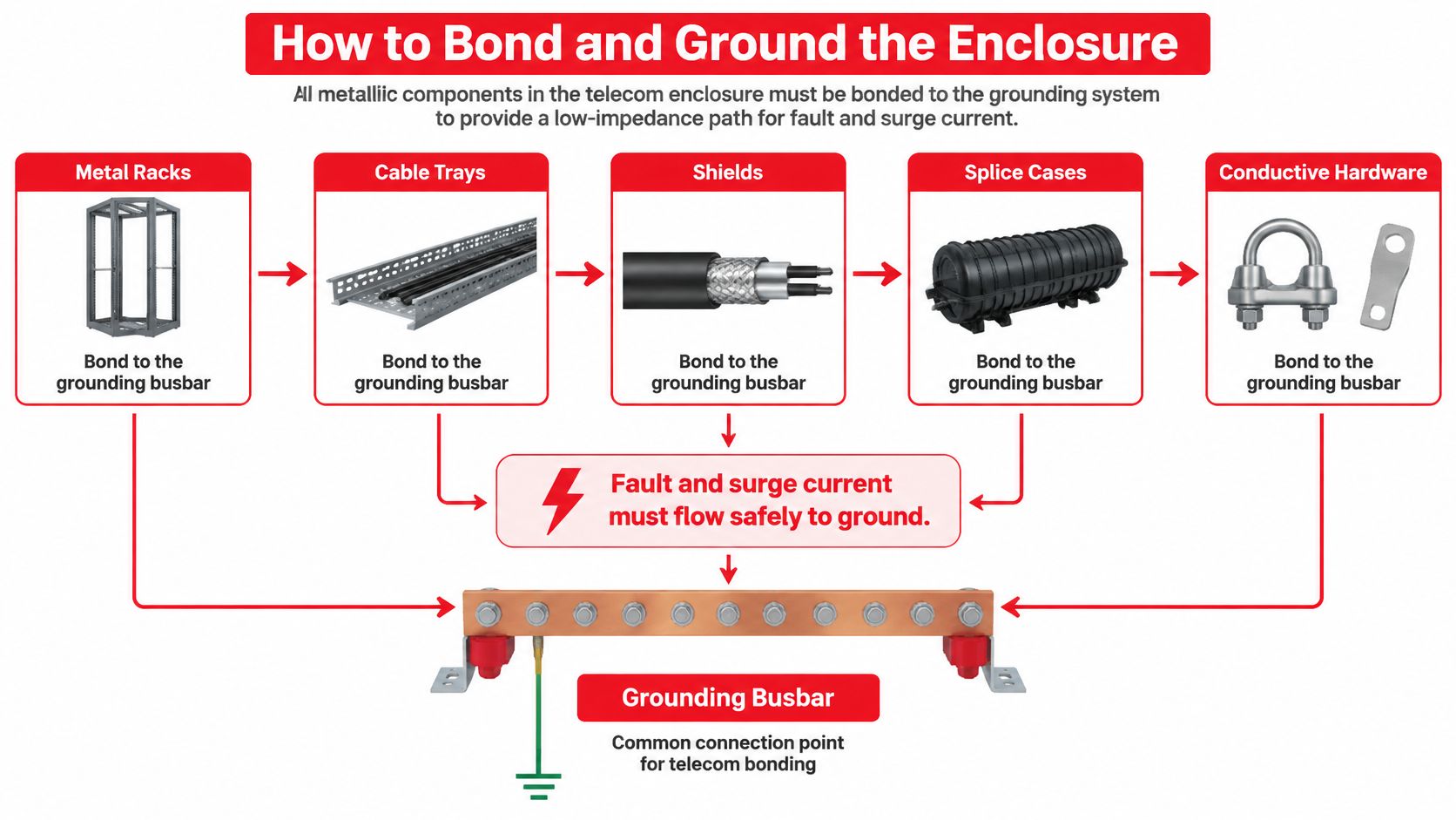
The enclosure's metallic components need an intentional connection arrangement, as this diagram illustrates.
Establish and verify the bonding path
Identify the serving busbar. Locate the Telecommunications Grounding Busbar, or TGB, or Telecommunications Main Grounding Busbar, or TMGB, shown on the approved design. Convenient nearby metalwork is not a substitute for the designated connection point.
Install a dedicated enclosure ground bar. Position it where lugs can be inspected, torqued, labeled, and serviced after the shelves are populated. A bar buried behind loaded patch panels may be correct on paper and unreachable in practice.
Size the bonding conductor and busbar from the approved design. Specify conductor material, stranding, termination method, and listed compression hardware as one assembly under the governing standard. Reserve busbar capacity for documented future connections instead of filling every position during initial buildout.
Prepare the contact surfaces. Remove paint where the approved connection requires bare metal, or use listed paint-piercing hardware. Paint left between mating conductive surfaces can increase resistance.
Connect the conductive components. Account for racks, raceways, runways, cable trays, shields, splice cases, and line protectors as applicable. Mounting screws and incidental contact should not be assumed to establish an acceptable bond.
Label each connection. Identify the conductor's origin and destination so maintenance personnel can trace it. An unlabeled conductor is difficult to distinguish from an abandoned or incorrectly routed connection.
Test continuity and record it. Have qualified personnel verify the installed bonding path using the approved test method and suitable equipment. Record the result with the connection location so later work can compare conditions after moves, additions, and changes.
Protect expansion capacity. Keep spare busbar connection positions accessible and show them on the drawing. Leave enough working room around the bar for the next conductor, the next lug, and the tool needed to land both.
For a visual supplement to the bonding workflow, use the following video alongside the approved project documents.
Mixed copper-and-fiber installations still contain conductive rackwork, hardware, and potentially metallic cable components. Show each intentional bond on the drawing so technicians do not mistake an incidental path for the designed connection. Treat the enclosure as one node in the building bonding system: if the bar cannot be reached, labeled, tested, and expanded after installation, the design is unfinished.
Fire Ratings, Materials and Handover Documentation
LSZH, or low-smoke zero-halogen, isn't a blanket compliance approval. It describes material characteristics, not automatic suitability for every plenum, riser, pathway, or jurisdiction. Evaluate the cable, enclosure components, penetrations, and installation environment together.
Think of each framework name you encounter on a datasheet the way you would think of different inspection trades on a job site: OFNP, CPR, UL, IEC, RoHS, and REACH each answer a different question, and none answers all of them. A declaration under one framework doesn't replace evidence required under another, so verify fire-performance listings and material declarations against the applicable local code and the product documentation for the exact item being installed.
Separate fire performance from material declarations
For North American projects, verify the applicable product listings and the required cable designation for the installation location. OFNP identifies an optical-fiber nonconductive plenum cable designation, not a general rating for the surrounding cabinet.
For European projects, determine the applicable CPR cable classification and relevant product standards. Review RoHS and REACH declarations separately for their material and substance requirements. Confirm the complete compliance route with the local authority having jurisdiction rather than selecting products from a certification-logo collage.
Paint, coatings, labels, grommets, and polymer accessories also belong in the review. A replacement label or field-added cable-entry component shouldn't be accepted solely because it physically fits.
| Inspection item | Evidence to retain |
|---|---|
| Cable suitability | Fire designation and approval for the installation environment |
| Enclosure and accessories | Applicable product certification and installation instructions |
| Materials | Manufacturer declarations for relevant components |
| Identification | Product model, serial numbers where provided, and label schedule |
| Local acceptance | Inspection requirements and documented approvals |
Procurement check: Ask for the actual certificate, declaration, or test documentation applicable to the supplied product, not just a catalog statement that a product family is compliant.
Make documentation useful after acceptance
Replaceable modules and standardized identification can help technicians change a damaged component without replacing the whole assembly. Proprietary hardware becomes a lifecycle risk when nobody can identify its replacement part, termination method, or compatible module.
Keep a handover package containing as-built drawings, flame-rating records, material declarations, product identifiers, fiber polarity maps, test results, and a change log. Associate those records with the installed location and cable labels.
A folder full of certificates isn't enough if the owner can't connect each document to the actual equipment. The handover package should let a future technician establish what's installed, where it connects, and what evidence supported its acceptance.
Specify the Enclosure Before You Order
Write a performance and dimensional specification before requesting a final quotation. A catalog part number doesn't explain how the enclosure will function inside the building, and an equipment list alone doesn't define the installation.
Build a coordinated purchase package
List current and planned connections by media. Identify copper termination categories, fiber trunk counts, connector formats, splice requirements, and patching arrangements. Distinguish installed capacity from equipped capacity so an empty shelf isn't mistaken for a usable connection.
Translate capacity into drawings. Include front elevations, side views, cable-entry locations, manager positions, and reserved module space. Enter the applicable clearance and pathway-fill criteria directly into the specification rather than leaving installers to infer them.
Record the enclosure type and environment. State whether the location is a conditioned room, unconditioned closet, or outdoor site. Identify access restrictions, security needs, mounting support, and the route for delivering and replacing the assembly.
Attach the bonding and compliance requirements. Identify the serving busbar, approved conductor arrangement, connection schedule, and expansion provision. Include the jurisdiction's fire-rating requirements and the product documentation needed for inspection.
Define supplier deliverables. Require dimensioned drawings showing the complete cable route, applicable certifications for supplied items, a commissioning test plan, and a handover-package template. Confirm local inspection requirements in writing before releasing the purchase order.
Resolve supplier questions before approval
Ask whether trays can be withdrawn with adjacent modules populated, whether rear connectors remain accessible, and whether doors close without contacting cable boots. Have the supplier identify which accessories are included, which require separate ordering, and which proposed substitutions change the usable service envelope.
At Southern Tier Resources, our Data Center Solutions provides infrastructure fit out for data centers and hyperscale cloud providers. To discuss the enclosure specification as part of a broader fit-out, customers can call (469) 405-4671.
Keep the approved drawings attached to the purchase package. If a supplier proposes a different cabinet or shelf, review its geometry and documentation before accepting it as equivalent.
Commissioning Checks Before Handover
Commission the installed assembly, not just the individual products. A compliant cabinet and tested cable can still form an unserviceable installation if the final routing, access, or records differ from the approved design.
Run these checks with the enclosure fully populated and its normal doors, covers, and accessories installed.
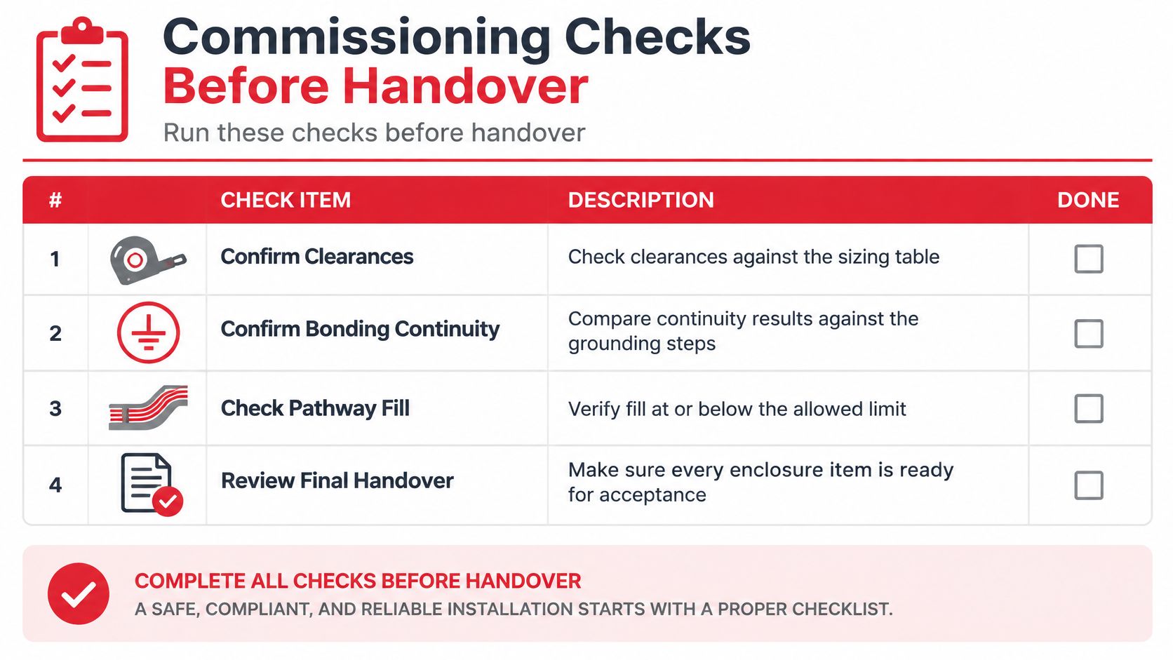
- Confirm clearances: Measure the completed working space, including obstructions introduced by adjacent equipment.
- Verify bonding continuity: Match recorded results to the installed connection schedule and investigate missing identifiers.
- Check pathway fill: Compare actual cable occupancy with the approved allowance for each pathway type.
- Inspect bend radius: Check fibers and patch cords at entries, managers, tray hinges, and closed-door contact points.
- Verify labels and polarity: Reconcile physical identifiers and fiber connections with the drawings and test records.
- Operate doors and trays: Confirm technicians can reach terminations without pulling neighboring cables.
- Capture changes: Record field modifications before accepting the final drawings.
- Collect the handover package: Confirm that each installed run and assembly has the required supporting records.
Use the checklist below as a completion aid, alongside the project-specific acceptance requirements.
Test the paths technicians will depend on
Have qualified personnel perform the bonding continuity test using the approved procedure. Record the measurement locations, instrument, result, and acceptance criterion so the owner can understand what was verified.
For fiber, inspect connector end faces with a suitable inspection scope, clean contaminated connectors, and reinspect before mating. Complete optical loss testing against the project's acceptance criteria, using the appropriate reference method and documented test configuration.
Save results under the permanent cable identifiers. A passing file with an unrecognizable filename is difficult to use during fault isolation.
Watch particularly for undocumented bonding extensions and drawings left unchanged after late field modifications. The first obscures the installed electrical connection arrangement; the second sends the next technician to the wrong port, pathway, or component.
Finish with a joint installer-and-owner walkthrough. Both parties should confirm that the physical installation, test results, and drawings agree, then archive the signed acceptance package for maintenance and future audits.
Southern Tier Resources provides engineering, construction, fiber splicing, testing, and data center infrastructure fit-outs to help turn an enclosure specification into a documented installation. Visit Southern Tier Resources to discuss your connection schedule, site constraints, and handover requirements before procurement.