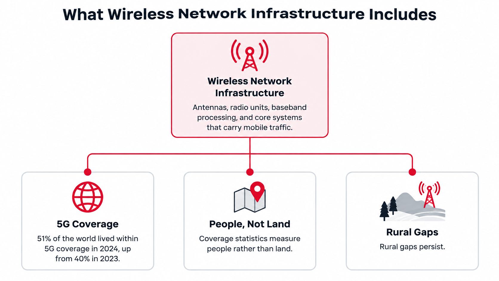
In 2024, 51% of the world's population lived within 5G coverage, up from 40% in 2023, according to the ITU's mobile network coverage data. Five years after the first commercial launches, half the planet sits inside a 5G footprint, and that figure is where most planning meetings begin.
It's also where budgets go sideways. Coverage percentages count people, not land, and they say nothing about whether a candidate site has power, a fiber route, a lease that survives renewal, or a crew that can reach it in February. Wireless network infrastructure is a power, transport and permitting business that happens to end in a radio.
Two numbers tell you whether a design is any good. Energy per delivered bit, tracked over a full year. And days from permit approval to live service. Both are unglamorous. Both predict whether the network earns its keep.
What Wireless Network Infrastructure Includes
A wireless service area depends on more than antennas. Its coverage and capacity rely on sites, radios, power, transport routes, permits and the equipment that connects the network to its core. Gaps between regions and between urban and rural areas reflect differences in investment, spectrum access and the ability to build fiber and power infrastructure.
An antenna provides the radio connection, while fiber and other backhaul carry traffic onward. The mobile core handles authentication, routing and policy. Adding radio capacity can be relatively quick; building a new transport route may require permits, trenching, splicing and surface restoration.
The chain from handset to core
Each component has a distinct role, location and build responsibility. Projects often cross several contracts and crews, so planners should map the dependencies before setting a schedule.
| Component | Role | Typical location | Usually built or run by |
|---|---|---|---|
| Antenna and radio unit | Converts digital signals to radio waves and back | Tower, rooftop or pole | Radio operator or tower company |
| Baseband processing (RAN) | Schedules and processes radio signals | Equipment room or cabinet | Carrier or RAN vendor |
| Macro cell | Provides wide-area coverage and base capacity | Tower or rooftop | Carrier or tower company |
| Small cell | Adds local capacity in dense areas | Streetlight, utility pole or building | Carrier or neutral host |
| Backhaul | Links the cell site to aggregation and the core | Fiber or microwave route | Carrier or fiber contractor |
| Fronthaul | Links radio units to baseband in split architectures | Fiber between cell site and distributed unit | Carrier or network vendor |
| Mobile core | Handles authentication, routing and policy | Regional data center | Carrier or cloud provider |
| Edge and data center integration | Hosts latency-sensitive applications close to users | Metro data center or edge cabinet | Carrier or data center operator |
For a new small cell, the build may involve a lease, pole attachment, power drop, fiber route, splice closure, radio, baseband card and maintenance agreement. Treat these as linked work packages: a radio can be ready while a delayed permit or fiber route holds up service. Sequencing the dependencies makes the delivery schedule more realistic.
How Traffic Moves from Antenna to Core
Follow one photo as someone uploads it from a phone on a street corner.
The handset encodes the file and pushes it over the air to the nearest antenna. The radio unit converts that radio signal into digital samples and hands them to baseband processing, which schedules the traffic against everyone else in the same cell. When the radio unit and baseband sit in different places, the samples cross fronthaul, usually fiber, occasionally a short microwave hop.
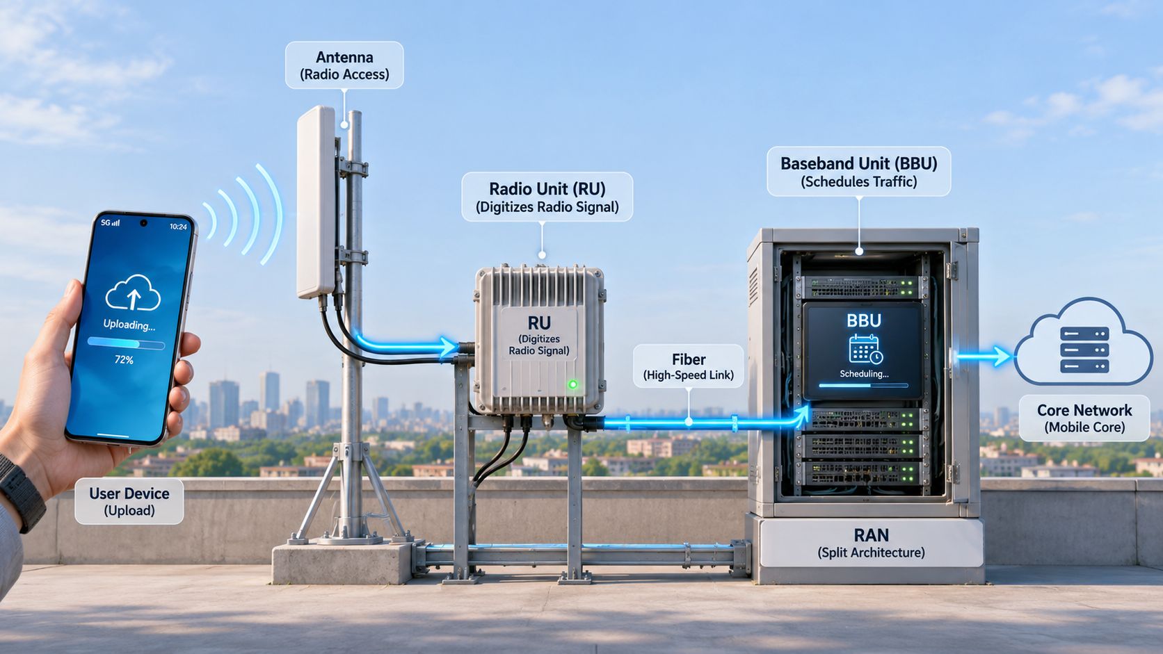
Baseband then pushes the traffic over backhaul to an aggregation point and into the mobile core, where the network authenticates the subscriber, applies policy and routes the packet either to the public internet or to an application hosted nearer the user.
Here's where transport decides everything. A cell whose radio can deliver far more than its backhaul can carry is a slow cell with fast hardware in it. No amount of antenna tilt repairs a missing fiber route, and no radio setting compensates for a saturated aggregation link.
Where the milliseconds accumulate
Air interface scheduling costs a slot or two. Short fronthaul adds a fraction of a millisecond, long fronthaul adds more and forces tighter synchronization. Backhaul across a metro adds several. Core transit and an internet exchange add a few more. Every hop you remove by moving compute to an edge cabinet buys latency back, and hands you a new set of problems: cabinet power, cooling, battery backup, physical security and a synchronization source that doesn't drift.
AI workloads reshape this path rather than merely filling it. CTIA's analysis of wireless and AI projects that AI-related wireless traffic will grow three times faster than overall wireless traffic and could represent nearly one-third of broadband traffic by 2034. Wireless data use in the United States reached 159.3 trillion megabytes in the latest annual survey, up 20% year over year, with overall demand projected to quadruple by 2032.
That matters because AI traffic is uplink-heavy and latency-sensitive in ways a downlink capacity plan never captures. A site serving inference requests from cameras or field devices stresses uplink scheduling, backhaul symmetry and power headroom long before it runs out of downlink throughput. If you're mapping the transport side of this, the scalable network architecture guide from PushOps is a solid primer on how aggregation layers stack up.
Map uplink demand and latency targets before you order radio hardware. Sequence it the other way and you'll buy radios that sit behind a link you can't upgrade for two budget cycles.
Matching Cell Types to Coverage and Capacity Goals
Cell choice sets the trade-off between reach, busy-hour capacity, power draw, site costs, and maintenance. A macro cell covers a broad area; a small cell adds capacity where traffic concentrates. Raising transmit power can extend reach, but it also increases interference. Splitting a sector improves frequency reuse and adds hardware to power and maintain.
3GPP's 5G energy efficiency framework treats energy efficiency as an operational objective alongside coverage, capacity, and quality of service. Densification adds active network elements, particularly high-band small cells with massive-MIMO radios. Radios with measurement-driven sleep modes and carrier shutdown can reduce their draw when demand falls.
| Cell type | Primary strength | Typical site | Best use |
|---|---|---|---|
| Macro cell | Wide-area coverage and base capacity | Tower or rooftop, high power | Rural areas and highway corridors |
| Small cell | Localized capacity | Streetlight, pole or building facade | Dense urban streets and transit hubs |
| Indoor distributed antenna system | Building coverage | Ceilings, risers and shared antennas | Offices, hospitals and venues |
| Massive MIMO radio | Capacity from many antenna elements | Macro or high-band small cell | Dense hotspots with mid or high band spectrum |
A decision sequence that holds up
Set the coverage obligation first, including requirements in licences or funding agreements. It defines the macro footprint and shows where the problem is reach rather than capacity.
Then map busy-hour demand by site. Look for sectors that cannot carry peak traffic and identify where users cluster, such as transit platforms, stadium aprons, hospital concourses, warehouse floors, or a few downtown blocks.
Add small cells only where the demand map supports the extra power, backhaul, and maintenance. If a site's load stays within capacity for most of the year, first consider scheduling, available spectrum, or a temporary capacity solution for the peak period.
A stadium makes the trade-off clear. It needs high capacity during events and far less between them. A permanent macro tower sized for event peaks may sit underused while still drawing power and incurring lease costs. An indoor distributed system, paired with small cells around the gates and coordinated licensed and shared spectrum, can serve event demand with lower lifecycle cost. A cellular coverage comparison for RVers illustrates how terrain and band choice affect coverage maps, though cell planning still needs site-specific demand and capacity data.
Power and Energy Per Bit at Every Site
The comfortable assumption is that energy follows traffic. Recent evidence says otherwise.
Cellular energy use is shaped more by hardware configuration, coverage obligations, capacity and traffic patterns than by data volume alone, and networks draw heavily during low-demand hours. Thunder Said Energy's cellular network energy analysis estimates global cellular electricity consumption at about 250 TWh annually in 2026, roughly 0.8% of global electricity demand and more than triple the 2015 level. It also reports that more than 80% of communications-service-provider energy consumption occurs in the radio access network, and that some 5G macro radio units use more than four times the power of comparable 4G units.
Read those together and the conclusion is uncomfortable: adding radios to handle a demand spike raises operating cost immediately and raises utilization only if the traffic arrives on schedule.
The checks that decide a site's power profile
- Busy-hour and idle budgets: size the rectifier and feeder for the busy hour, but record the idle draw too. It's the idle number that erodes margin over a year.
- Battery runtime against real outages: match backup duration to the outage profile on that feeder, not to a default. If generator backup is on the table, weigh outage runtime, fuel, and maintenance costs from Amp'd Energy Solutions before you commit cabinet space to it.
- Thermal headroom: cabinets and rooftop shelters fill up with radios, and cooling capacity rarely gets the same scrutiny as radio count.
- Sleep-mode behaviour: measure wake-up time and its effect on mobility. Aggressive shutdown creates coverage holes and slow recovery at exactly the moment a handover needs to succeed.
- Telemetry: if you can't read power state, temperature and traffic remotely, you can't tune any of the above.
Two sites, one budget
Picture two operators facing the same spike in a downtown block. The first adds radio carriers to every sector to cover the peak, running all of them flat out around the clock. The second keeps the same peak capability but stages it, activating capacity on a schedule tied to measured demand and letting idle carriers sleep with tested wake-up behaviour.
Both pass the drive test. The first carries a permanently higher energy bill, more heat in the cabinet and shorter battery runtime when the grid drops. The second needs better telemetry, tighter configuration discipline and staff who understand the wake-up path. That's the actual trade: capital simplicity against operating efficiency.
Track energy per delivered bit, per site, over twelve months. Coverage percentages and peak throughput flatter a network. Joules per gigabyte tells you the truth.
From Site Survey to Live Service
A radio plan can be ready while a site remains months from service. The schedule depends on power, transport and approvals as much as antenna placement, so each build stage needs a clear exit check.
Steps one to four, the ground game
1. Survey candidate sites against targets. Check RF objectives, available fiber routes, electrical service and structural loading before designing a radio. Exit check: a site list with written RF and fiber feasibility for each location.
2. Secure the site. Use a lease, pole-attachment agreement or tower contract, depending on the site. Exit check: an executed agreement with renewal terms and access rights for maintenance crews.
3. File permits and complete make-ready. Account for zoning, historic and environmental reviews, pole replacement, utility upgrades and rights-of-way approvals. The Federal Register's discussion of 5G deployment constraints identifies mid-band spectrum availability and the fiber buildout needed to support small cells among the constraints. Exit check: permits are in hand and make-ready is signed off before construction begins.
4. Build power, cabinets, grounding and the fiber route. Choose aerial or underground construction based on route availability, cost and restoration risk. The trade-off is practical: a route that is easier to build may be harder to maintain or restore. Exit check: energized service and a continuous, tested fiber path to the aggregation point.
Steps five to eight, hardware into service
5. Install radios and antennas. Set azimuth and tilt to the RF plan, then record the installed configuration. Exit check: as-installed orientation is documented, and passive intermodulation and voltage-standing-wave-ratio tests pass.
6. Connect backhaul and prove the fiber. Splice the route, then test optical loss and reflectance on every strand. Skipping those tests can leave splice losses undiscovered until traffic reaches the link. Fiber construction, splicing and testing are part of the delivery chain; Southern Tier Resources provides engineering, design, construction and maintenance for wireline and wireless communications, with turnkey wireless deployment capabilities.
7. Run acceptance tests. Test coverage, throughput and latency at busy hour, along with synchronization against the timing source. Exit check: a signed test report against the contracted KPIs.
8. Deliver as-builts and hand over to maintenance. Include configuration records, fiber-route documentation and alarm ownership. Exit check: records match the installed plant, and every alarm has a named owner.
The step people underestimate: make-ready. Pole replacements, utility work and rights-of-way approvals can outlast construction, and are difficult to compress once delayed.
Cost drivers, in rough order of weight, include lease terms, permit fees, make-ready, fiber construction and electrical service. Plan safety controls for RF exposure, tower climbing and lockout procedures before crews arrive.
Measure the route to live service, not the hardware count. Track days from permit approval to activation, fiber-route availability, backhaul capacity, synchronization quality and sustained busy-hour performance per site. Those measures show whether the build is delivering service on schedule and whether the transport path can carry the load.
Trends Reshaping Wireless Infrastructure Upgrades
Four shifts are changing what gets built, and each forces a physical change rather than a software toggle.
5G standalone cores with mid-band spectrum push investment toward cloud-native core sites and denser fiber transport. The skill is transport engineering and core integration. The risk for plans written today is a core architecture that assumes fiber capacity nobody scheduled.
Open RAN splits the radio unit, distributed unit and centralized unit across open interfaces. More vendor combinations mean more interoperability testing at every site, and more integration skill on the crew. A design that assumes one vendor's stack will talk to another's is a design waiting for a lab report.
CBRS shared spectrum in the 3.55 to 3.70 GHz band depends on Spectrum Access System coordination, which turns small-cell placement and transmit power into a coordinated process with other users. Site planning becomes a coordination workflow, not a spreadsheet. Skip it and your coverage prediction is fiction.
Private networks for factories, campuses and ports bring their own core, local edge compute and on-premise power, often on a faster timeline than public builds. The skill is end-to-end integration with the operator's own IT and safety systems. The risk is treating a private build as a smaller version of a public one when the power and reliability expectations are higher.
Together these trends argue for phased builds. Leave conduit, rack space, power capacity and fiber count for the upgrade you can't name yet.
Confirm Your Site Plan Before You Commit Budget
A site can meet its radio targets and still miss its launch date if fiber, power or permits are not ready. Before committing budget, document five items: the coverage obligation, busy-hour capacity per site, fiber route availability, power capacity including battery backup, and a permit timeline the schedule can absorb.
Check each item against the build. Compare the coverage map with the RF plan, and forecast capacity at the busiest hour rather than from average traffic. Confirm the fiber route and splice plan with the construction team. Check the equipment list against available power and cooling, and assign an owner to every permit milestone.
The plan must also account for what happens after launch. Set out how faults will be handled, how performance will be monitored, and how changes will be recorded. Keep as-built documentation current so maintenance crews can work from the installed configuration.
Southern Tier Resources provides end-to-end services from engineering and design through turnkey wireless deployment and ongoing maintenance. Its work includes wireless deployment and engineering, construction and maintenance for wireline and wireless communications. Share the site list, coverage targets and power data to scope the build against the actual fiber, power and permit requirements. Southern Tier Resources can support the project from design through deployment and maintenance.