A cable splicer is a skilled technician who joins communication or electrical cables, most commonly using fusion splicing for fiber-optic strands, to restore or extend network links with minimal signal loss. If you've ever heard the term and pictured only one kind of field job, that's the first mistake to clear up, because fiber and copper splicing are related work, but they're not the same trade.
What makes the role confusing is that the title survived several generations of network technology. The work started in telephony and power systems, then evolved with fiber optics, automated splicing machines, and dense backbone networks that can't tolerate sloppy joints.
What Is a Cable Splicer and Why the Role Evolved
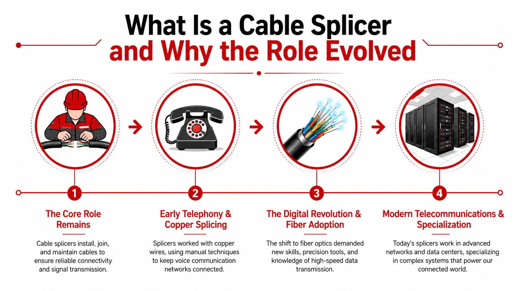
What is a cable splicer, exactly? It is the technician who makes damaged or separate cables behave like one continuous line again. In fiber networks, that usually means preparing, aligning, and permanently joining optical strands so the splice adds as little loss as possible.
From field repair to precision work
The title has older roots in telephone and electrical work, where splicing required steady hands and careful judgment. In the late 1950s, products such as the 3M Scotchlok connector were introduced to simplify splicing of steel-core cables, which shows how long the industry has pursued faster and more repeatable field methods. Optical systems raised the bar even higher, because fiber does not tolerate rough handling the way older copper systems sometimes could. (Fibre optics through time)
Single-mode fiber had already emerged by 1980, and that shift created the need for far more precise splicing than older methods could deliver. Fujikura developed the first arc fusion splice machine in 1978, then launched the world's first fully automated arc fusion splicing machine in 1985. That 1985 system introduced Profile Alignment System, or PAS, which became common in modern splicing machines. (Fujikura arc fusion splicing history)
Practical rule: if a network depends on low-loss, high-reliability joints, the splice has to be treated like a precision optical task, not a quick repair.
Why the shift mattered
Older mechanical splices used a connecting jelly in a casing, but they were not suitable for long-distance transmission because of higher losses. That is why the role changed from “make the cable work again” to “protect the optical budget across a long route.” In modern carrier, broadband, and data-center environments, a splice is part of the network's performance, not just a repair point.
The historical milestone in Chicago helps explain the scale of that change. In 1977, the first optical telephone communication system was installed there, and each fiber carried the equivalent of 672 voice channels. As networks moved from voice circuits to backbone fiber, the quality of each splice became central to keeping those links stable across cities, regions, and continents.
That is why the modern cable splicer sits between two worlds. The job still includes repair work, but in fiber-heavy networks it is also a precision discipline tied directly to throughput, uptime, and long-haul connectivity.
Fiber Splicing Versus Copper Splicing
The fastest way to misunderstand this job is to treat fiber and copper splicing as interchangeable. They both involve joining cables, but the materials, tools, standards, and failure modes are different enough that a technician usually needs separate training before moving from one to the other.
What changes between the two trades
Fiber splicing joins glass or plastic optical strands, usually single-mode G.652/G.657 or multimode G.651, with performance measured in splice loss and return loss. In field-grade fusion splicing, practical specifications commonly sit around 0.01–0.03 dB typical splice loss and >60 dB return loss, because lower loss helps preserve the optical link budget and reduces rework. (Legacy Fiber Optics fusion splicer specs)
Copper splicing joins conductive metal wires, often with connectors, crimps, or solder. The technician is usually checking continuity, insulation resistance, and environmental sealing, not optical loss. The finished joint has to survive vibration, moisture, and handling, but it doesn't need the same microscopic alignment required for fiber.
| Attribute | Fiber Splicing | Copper Splicing |
|---|---|---|
| Material joined | Optical glass or plastic strands | Conductive metal wires |
| Typical methods | Fusion splicing, mechanical splicing | Connectors, crimps, solder |
| What gets measured | Splice loss, return loss | Continuity, insulation resistance, sealing |
| Typical field environment | Carrier plant, broadband buildouts, data centers | Telecom, utility, alarm, and general cable work |
| Skill emphasis | Cleaving, alignment, cleanliness | Termination, conductor integrity, insulation handling |
Why a technician can't just switch over
A fiber technician needs a steady hand, clean prep habits, and a feel for optical inspection. A copper splicer needs a different toolkit, a different way of judging failures, and often different safety procedures depending on voltage and application. The overlap is real, but it's narrower than most hiring managers think.
That distinction matters for carriers, ISPs, and data-center operators because the wrong assumption leads to bad staffing decisions. A crew that's excellent on fiber backbone work may not be the right fit for copper plant, and a utility splicer trained on underground power systems isn't automatically ready for optical transport work. Government occupational descriptions also make the scope broad, since splicers can work on communication, data, alarm, and high-voltage underground systems, often in manholes, vaults, or energized circuits. (Occupational info on cable splicers)
A good hiring question is simple, what exactly did this person splice, what tools did they use, and how was the work tested afterward?
Where the confusion comes from
The title stayed the same while the work diverged. That's why a reader searching for what is a cable splicer often lands on mixed definitions that blur telephone work, utility work, coax, and fiber. In practice, the name is broad, but the job description on a real project should be specific to the medium, the loss target, and the test method.
How Fiber Fusion Splicing Works Step by Step
Fusion splicing looks clean when it's done right, but the finished joint is the result of a very controlled sequence. Skip one step, and the splice may still light up, just with higher loss, weaker reliability, or an ugly trace that comes back during acceptance testing.
The prep work matters as much as the splice
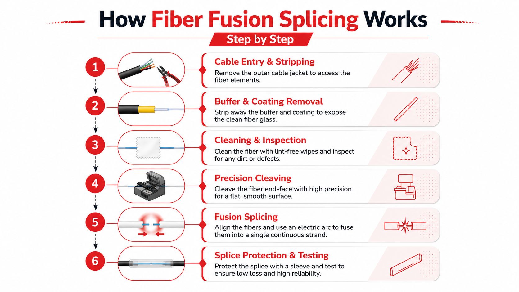
The first part of the job is cable entry and stripping. The technician opens the cable, separates the fibers, removes the buffer and coating, then cleans the bare glass. That cleaning step sounds basic, but dust, gel, or coating residue can interfere with the arc and weaken the joint.
Next comes cleaving. The fiber has to break on a flat, precise surface, because a bad cleave angle can push splice loss beyond the tight field expectations used in professional work. After that, the stripped fibers are placed into the machine, aligned, and inspected before the arc joins them.
What happens during fusion
Fusion splicing uses heat to permanently melt the fiber ends together. The point isn't to “glue” them, it's to create a joint that behaves like a continuous strand. The final splice is then protected with a heat-shrink sleeve so the bare glass isn't exposed to handling or vibration.
Clean prep is cheaper than rework. If a splice fails, the problem often started before the machine ever fired an arc.
A simple field sequence
- Open the cable and stage the fibers. The technician gets access without nicking the buffer tubes or stressing the strand.
- Remove coating and residue. The bare fiber has to be clean enough for accurate alignment.
- Cleave the fiber. This creates the end face the splicer will join.
- Load and align the fibers. The machine centers them before the arc.
- Fuse the ends. Heat joins the fibers into one continuous path.
- Protect and test the splice. A sleeve, then verification, keeps the joint stable in the field.
Mechanical splicing still has a place in quick repairs, especially when low loss is less critical than speed. But for the backbone and distribution work most carriers care about, fusion splicing is the standard path because it gives the reliability and low-loss performance the network expects.
A new hire should remember the core pattern: prep, clean, cleave, align, fuse, protect. Everything else is detail around those six actions.
Essential Tools and Testing Equipment for Cable Splicers
A good splice starts with the machine, but the machine is only one part of the setup. The technician also needs a cleaver, cleaning supplies, light-testing gear, and a way to document what was done so the work can be accepted and traced later.
The fusion splicer itself is usually judged by field speed, recordkeeping, and consumable life, not just brand. Modern units can complete a splice in about 6–8 seconds and a heat-shrink cycle in about 9–25 seconds. They can also store 2,000–5,000 splice records and images, which matters when a carrier wants traceability or when a data-center team needs clean as-builts. Electrode life can range from roughly 5,500 arcs to 38,000 splices, and blade life can exceed 77,000 cleaves on some platforms. (Fusion splicer operational benchmarks)
Those numbers translate directly into field outcomes. Faster cycles shorten outage windows during cutovers, longer electrode and blade life lowers cost per splice, and built-in storage keeps photos and records attached to the job. When a crew is working across a carrier route or inside a live facility, that paperwork can matter as much as the joint itself.
What belongs in a working kit
- Fusion splicer: Joins the fibers and often handles alignment automatically.
- High-quality cleaver: Creates the square end face the splice depends on.
- Optical power meter: Confirms the link is delivering expected light levels.
- OTDR: Shows reflections and events so the crew can find a bad splice or connector.
- Cleaning tools and inspection gear: Keeps contamination out of the splice path.
- Tablet or job management system: Stores images, labels, test results, and acceptance data.
An experienced crew usually evaluates equipment by workflow, not sticker price. If a machine is fast but awkward to document, it can slow the project later when the customer asks for trace files and photos. That's why procurement should look at splice speed, storage capacity, consumable life, and how easily the machine fits into testing and reporting.
If you want a practical, field-level walkthrough of the splice process and test mindset, Southern Tier Resources has a concise guide on how to splice fiber optic cable that matches the way crews work on site.
The best tool list is the one that gets the splice done, proves it passed, and leaves a record someone else can audit later.
Certifications and Training Pathways for Cable Splicers
A person can learn the mechanics of splicing on the job, but that doesn't make them ready for every site. Good crews pair hands-on training with proof that the technician understands fiber prep, testing, and documentation under pressure.
What employers usually look for
Carriers and data-center operators care about three things. First, can the technician prep and splice cleanly. Second, can they interpret an OTDR trace well enough to spot a problem. Third, can they document the work without creating a mess for the acceptance team.
Formal certification helps because it gives hiring managers a baseline, especially when the crew will work on carrier-grade plant or inside live facilities. It doesn't replace field judgment, but it does show the splicer has been trained on the core process instead of learning only from trial and error.
A practical training path
The most useful path usually starts with supervised fiber handling, then moves into controlled splice practice, then test interpretation, then live work under review. A new hire should be able to explain why a bad cleave, dirty fiber, or poor protection sleeve can create trouble later, not just how to press the machine buttons.
Once that base is in place, the technician should be tested on trace reading, recordkeeping, and job closeout. If a team is trying to evaluate whether its training program is paying off, measure training ROI effectively is a useful framework for tying instruction to actual field outcomes.
Classroom knowledge matters, but the field teaches timing, cleanliness, and judgment faster than any slide deck ever will.
For hands-on validation, a manager can also use a structured test process instead of relying on confidence alone. Southern Tier Resources offers a practical reference on how to test fiber optic cable that fits well with a technician's early development.
What a resume should show
Look for specific fiber types, real splice environments, and evidence of testing responsibility. A splicer who has only seen lab conditions is not the same as one who has worked through dusty vaults, tight closets, or active data halls. The strongest candidates usually describe the medium they worked on, the testing they performed, and the conditions they were trusted to handle.
Safety Practices and Quality Assurance Standards
Safety and quality control are part of the same job in splicing. If the crew skips one, the other usually fails later, and the failure shows up in the field, not in the shop.
The hazards are real even when the work looks small
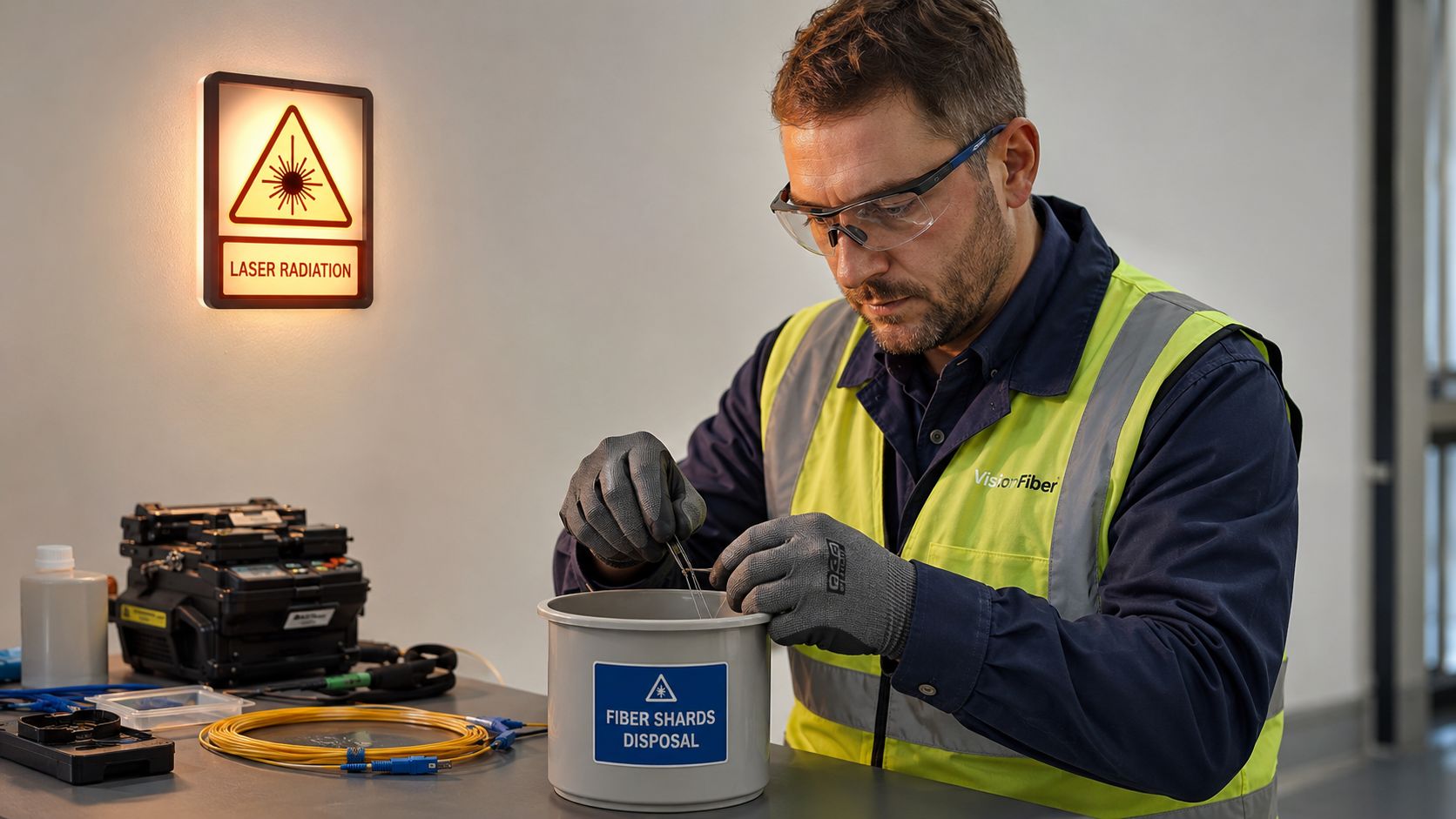
Fiber shards are tiny, but they're still glass, and they need to be handled with care. Laser safety also matters because the fiber path can carry invisible light even when nothing on the outside looks active. On utility or underground power work, the risks expand to arc-flash and energized-circuit exposure, which is why those crews follow stricter electrical safety rules and PPE requirements.
Good field practice starts with the basics, safety glasses, gloves, and a clean, controlled work area. In outdoor or underground environments, crews also need environmental discipline, because dirt, moisture, and cramped access points can turn a routine splice into a poor one very quickly.
QA is what keeps the splice from becoming a future ticket
The documentation trail matters because customers want proof, not just reassurance. That usually means splice loss logs, OTDR traces, as-built records, and photo documentation that show exactly what was installed and where. Without those records, a crew may finish faster today and spend far longer later trying to prove what happened on the route.
Practical rule: if a splice can't be tested and documented, it isn't really finished.
Carriers and data-center teams often expect the work area itself to support safe, repeatable operations too. Clear signage helps, especially around maintenance windows, access restrictions, and live work areas. Resources like Evright Industrial safety signage are useful reminders that visible controls are part of a disciplined field setup, not an afterthought.
Skipping QA shortcuts saves minutes and creates uncertainty that lasts for the life of the route. A clean splice with records attached is easier to accept, easier to troubleshoot, and easier to defend when someone asks what changed after the cutover.
When to Hire a Cable Splicing Specialist
The decision isn't really “in-house or outsourced.” It's whether the work is simple enough for your team's current skill set, or risky enough that you need a specialist who already works at that level every day.
A simple decision framework
Routine maintenance splices are usually the easiest place for internal crews to build capability. Those jobs often involve known plant, limited scope, and enough schedule control to allow careful prep and testing. But backbone cutovers, metro expansions, and data-center fit-outs carry a different kind of pressure, because the splice is tied to live service, tight windows, and a lot of downstream coordination.
That's where an established telecom infrastructure partner becomes useful. Southern Tier Resources, for example, provides fiber optics contractors for projects that need engineering, construction, splicing, testing, and documentation under one accountable team.
Questions that separate a specialist from a general contractor
- What medium are they working on? Fiber, copper, coax, and underground power are not interchangeable.
- Who owns testing and closeout? The crew that splices should also know how the job will be accepted.
- Can they document cleanly? As-builts and trace data matter when the route goes live.
- Do they understand your environment? Data centers, carrier huts, metro plant, and utility vaults all punish sloppy assumptions.
If you're evaluating a site with dense network dependencies, it helps to look at real infrastructure examples like the Barcelona cable landing station listing. Sites like that show how much coordination sits behind major connectivity work, and why a splice team has to fit into a larger engineering and testing process.
When in-house makes sense and when it doesn't
Build internal capability when the work is repeatable, the volume justifies training, and your team can maintain tools and records properly. Bring in a specialist when the route is high-stakes, the schedule is compressed, or the job requires both fiber expertise and broader construction coordination. The safest choice is often the one that reduces handoffs, because every extra handoff creates another place for loss, delay, or missing documentation.
Southern Tier Resources supports fiber builds, testing, and documentation for carriers, ISPs, data centers, and enterprise teams that need splicing done as part of a larger network project. If your job needs one accountable partner from construction through closeout, visit Southern Tier Resources and see how their field teams fit into your network plan.