The most popular advice about broadband network design is also the least complete: build fiber to as many premises as possible, then add capacity when demand appears. That approach treats the access drop as the network, while ignoring the transport paths, interconnection points, power systems, and operational records that determine whether the service remains usable at peak demand or after a failure.
A modern build has to work as one system. Access, middle-mile transport, regional routing, cloud interconnection, outside plant, and maintenance documentation all influence cost and service quality. The engineering question isn't just how to pass premises. It's how to move application traffic across a resilient physical and logical topology without exhausting optical budgets, route diversity, or operational visibility.
Redefining Modern Broadband Network Design
Last-mile fiber remains important, but it isn't automatically the principal bottleneck. A network can have an excellent fiber drop and still deliver poor service if the aggregation layer is undersized, the regional route is indirect, or the peering strategy forces cloud traffic through a congested handoff.
The demand model has changed. Residential connections now support many devices, continuous streaming, telehealth, business applications, and emerging AI, augmented reality, and virtual reality workloads. A Fiber Broadband Association report on middle-mile redesign warns that projects continue to rely on outdated assumptions instead of modeling real-world demand patterns, and it identifies insufficient middle-mile infrastructure in rural America as a barrier that raises access costs.
That observation changes the design sequence. Start with service geography and application behavior, then work backward through aggregation, middle mile, access, and premises equipment. If planners begin with a fiber count alone, they risk optimizing the least representative part of the system.
The access network is only one layer
A practical broadband network design separates at least four engineering questions:
- Access reach: Can the optical plant serve the intended premises within the available power budget?
- Aggregation behavior: Can access nodes hand traffic toward the core without creating a shared choke point?
- Middle-mile capacity: Can regional routes handle busy-hour demand and future service expansion?
- Interconnection quality: Can subscribers reach cloud, content, enterprise, and public-service destinations through sensible paths?
Each layer has a different failure mode. Access failures often involve fiber cuts, connector contamination, poor splices, or insufficient optical margin. Transport failures may involve route concentration, overloaded links, or a lack of physical diversity. Routing failures can leave a healthy optical plant unable to reach important applications.
Practical rule: Design the service path end to end, not cabinet by cabinet.
Oversubscription needs an application model
Oversubscription isn't necessarily bad. It becomes dangerous when planners apply a household average that hides simultaneous use. A community with heavy video, telehealth, business connectivity, and machine-generated traffic can produce a very different peak profile from a community modeled only by subscribed access rates.
Municipalities and ISPs should therefore document expected application classes, busy-hour behavior, business clusters, public facilities, and likely cloud destinations. The resulting model should drive feeder capacity, aggregation placement, route diversity, and peering decisions. The strongest access build can't compensate for a middle mile that was designed around diluted averages.
Core Architectures and Optical Power Budgets
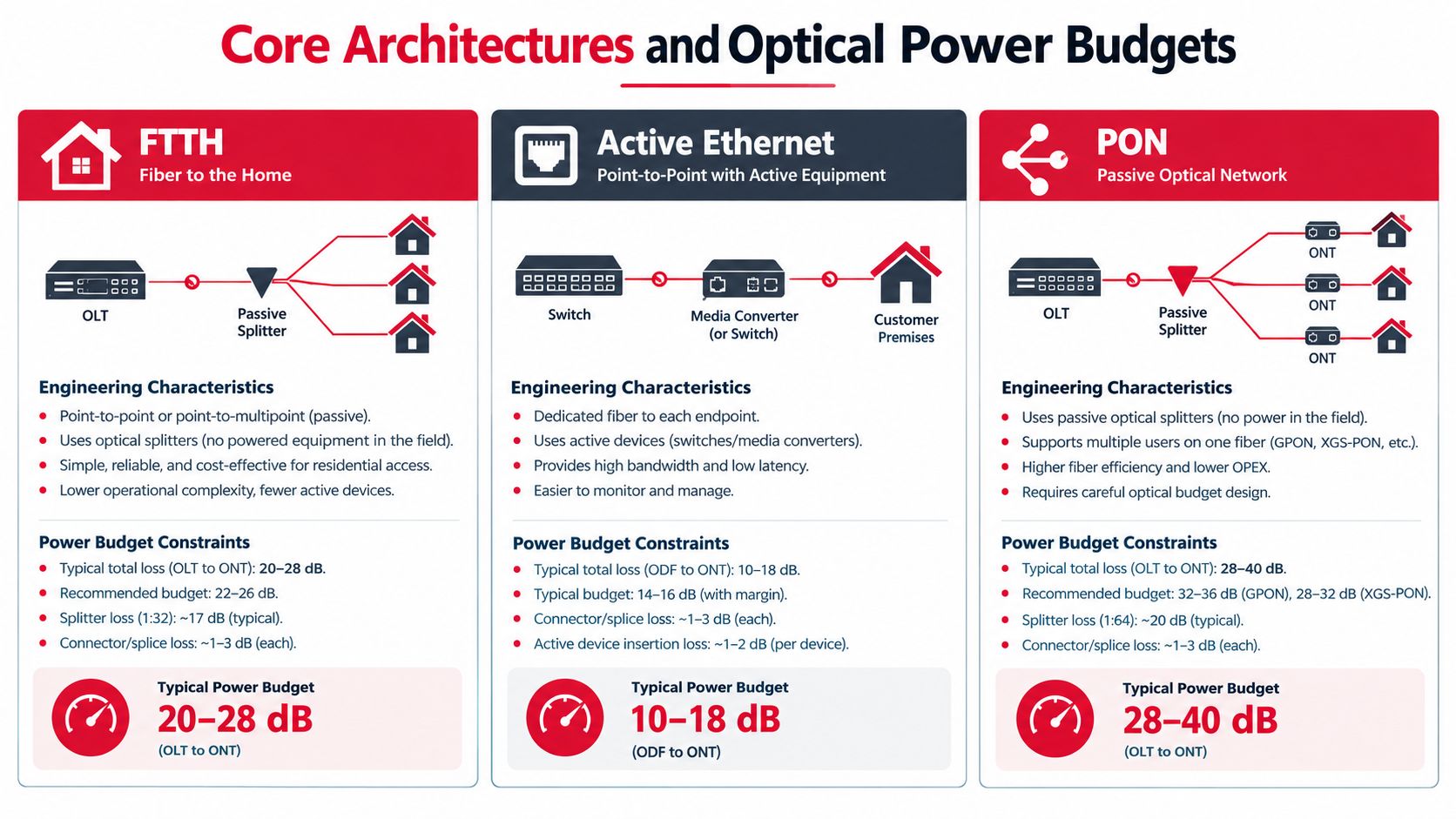
Architecture selection should follow geography, service obligations, maintenance capability, and upgrade plans. FTTx describes where fiber terminates, while Active Ethernet and PON describe how the access network distributes service. Those categories overlap in deployment discussions, but they create different operational and optical constraints.
Choosing between shared and dedicated access
A PON uses passive optical splitters to share feeder capacity among subscribers. That reduces active field equipment and can simplify outside plant power requirements, but the splitter chain consumes optical budget. Active Ethernet gives each subscriber a more dedicated logical path and can make troubleshooting and capacity allocation more direct, but it requires powered field electronics, suitable sites, and a stronger maintenance model.
FTTH and FTTB can both use PON or Ethernet. FTTH takes the optical connection to the premises, while FTTB terminates fiber at a building and uses an internal distribution method for the final connection. The right answer depends on building density, property access, internal cabling, service control, and the operator's ability to maintain active equipment.
Split ratios are budget decisions
XGS-PON supports about 9.953 Gbps of symmetrical capacity per port, as documented in the AXING GPON and optical access guidance. That figure describes shared port capacity, not a guaranteed rate for every subscriber. The engineering result depends on subscriber behavior, service profiles, split ratio, feeder design, and upstream aggregation.
Common deployed split ratios are typically 1:32 to 1:64 rather than the theoretical maximum. A 1:32 split has published splitter losses of roughly 17 to 18 dB, while 1:64 can reach roughly 20 to 21 dB, according to the same technical guidance. Increasing the ratio lets one PON port serve a denser footprint, but it leaves less margin for distance, connectors, splices, aging, repairs, and future changes.
| Architecture choice | What it favors | What it makes harder |
|---|---|---|
| PON | Passive field distribution and efficient shared access | Power-budget control, shared capacity planning, fault isolation |
| Active Ethernet | Dedicated logical paths and flexible service engineering | Field power, cabinet resilience, equipment maintenance |
| FTTH | Direct fiber reach to the customer location | Premises access, drop construction, restoration logistics |
| FTTB | Dense buildings with centralized internal distribution | Building-owner coordination and in-building plant control |
The correct split ratio isn't the one that serves the most addresses on paper. It's the ratio that preserves reach, service guarantees, and upgrade headroom under real construction tolerances. Before finalizing the bill of materials, review fiber handling, termination, and recovery practices through this fiber optic installation guide from Reworx Recycling, particularly when the project team is standardizing field work across contractors.
A dense split saves ports only when the optical margin and operating model can support it.
Middle-Mile Topology and Physical Latency Constraints
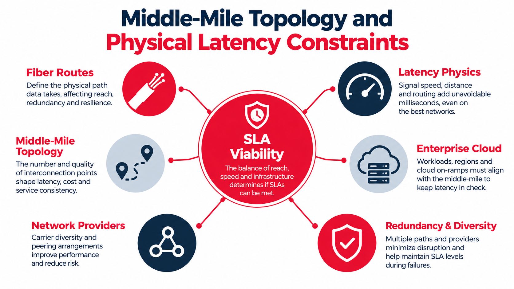
A last-mile network can be fully built and still underperform if its middle mile takes an unnecessarily long physical route or funnels multiple access areas through one vulnerable corridor. Middle-mile topology determines how efficiently the access layer reaches the core, the internet, enterprise sites, data centers, and cloud on-ramps.
Optical transport introduces about 5 microseconds of delay per kilometer, as described in the ETSI F5G-Advanced transport paper. That delay is small in isolation, but it accumulates with route length and combines with switching, queuing, processing, and application behavior. For low-latency services, physical route selection matters as much as nominal link capacity.
Build topology around failure domains
A regional network usually needs more than a simple spoke from each access node to a central site. Rings, diverse point-to-point paths, and strategically placed aggregation sites can limit the number of subscribers affected by a single cut. However, a ring isn't automatically resilient. If both directions share the same bridge, duct, pole line, or crossing, the logical redundancy may disappear during a single physical incident.
Map the actual civil corridors. Record bridge crossings, rail crossings, river crossings, utility corridors, road projects, and locations where construction crews are likely to encounter congestion. Then test whether the proposed paths remain diverse after those shared segments are removed.
Model traffic by destination
Middle-mile capacity planning should identify where traffic goes, not just how much access capacity exists. A network may need strong paths toward regional internet exchanges, cloud facilities, enterprise clusters, public institutions, and wireless aggregation sites. A local access node that has ample downstream capacity can still suffer if its uplink toward the dominant application destinations is constrained.
Use a traffic matrix that distinguishes residential, enterprise, municipal, wireless, and data center flows. Test ordinary busy-hour operation as well as a route failure, maintenance event, and major application shift. This exposes whether the design depends on one preferred path or can move traffic without creating unacceptable queues.
Keep the transport layer clean
Shorter physical paths, fewer regenerations, and clear transport boundaries simplify both latency management and fault isolation. Engineers should place regeneration and optical-electrical-optical conversion where the route and budget require it, not as a substitute for disciplined topology.
Design test: Remove the most convenient route from the model. If the remaining path can't carry essential services, the design has diversity on paper, not in operation.
Site Selection and Make-Ready Engineering
Outside plant decisions become expensive when teams postpone them. A route that looks efficient in GIS can fail during field verification because a pole lacks usable space, a cabinet site has no practical power path, or an existing duct is occupied, damaged, or inaccessible.
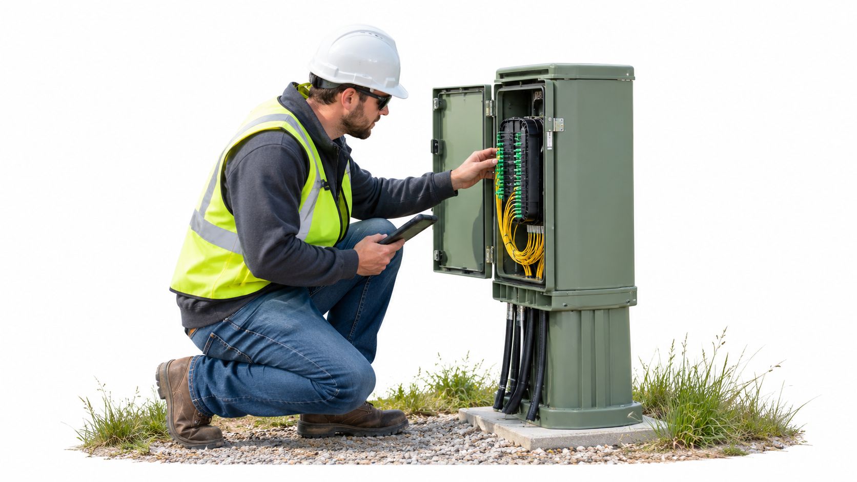
Verify the physical route before final design
A reliable site-selection process combines desktop records with field evidence. Check pole ownership, attachment space, structural condition, communications clearance, access rights, flood exposure, drainage, vehicle access, and proximity to existing utility power. For buried routes, confirm duct occupancy, bore feasibility, crossing requirements, and restoration obligations.
Make-ready engineering deserves its own schedule and budget. Pole loading, rearrangement, replacement, guying, grounding, and communications-space conflicts can change a route after the design appears complete. The same applies to cabinet locations. A pad that fits equipment dimensions may still fail because technicians can't open doors safely, generators can't reach it, or the site can't shed heat.
Treat power and thermal conditions as network inputs
Remote huts and cabinets need a power plan that reflects the service role. Identify normal supply, battery support, generator connection, grounding, surge protection, monitoring, and restoration access. A critical aggregation site should not depend on a single unverified utility arrangement.
Thermal management also requires field attention. Enclosures exposed to direct sun, dust, flooding, or poor airflow can shorten equipment life and increase alarms. Select sites where technicians can inspect and service equipment without unsafe roadside work or repeated traffic control.
A practical design review should ask:
- Can crews reach the site in all expected weather conditions?
- Is the power source documented and physically confirmed?
- Can the enclosure handle the installed equipment and future additions?
- Does the route maintain physical separation from its intended protection path?
- Are permits, easements, and utility-owner approvals aligned with construction timing?
The Southern Tier Resources team can be considered alongside other qualified contractors when a project needs coordinated wireline construction, fiber splicing, testing, and maintenance across the deployment lifecycle.
The field sequence matters. Verify the route, resolve make-ready conflicts, confirm utility and property approvals, then release construction packages. Releasing crews against an unverified route shifts design uncertainty into change orders, idle time, and rushed field decisions.
The following field perspective is useful when reviewing physical access, enclosure condition, and technician workflow:
Backhaul and Peering for Cloud-Dense Traffic
Backhaul is no longer a passive connection between an access network and an internet gateway. It is the transport fabric that carries residential, enterprise, wireless, cloud, and data center flows toward destinations that may change quickly.
Operators are moving from expansion alone toward optimization, with reliability, densification, visibility, and transport efficiency receiving more attention as AI workloads, hyperscale data centers, edge computing, and cloud connectivity intensify demand. CableLabs' coverage of OFC 2026 broadband trends identifies hollow-core fiber, distributed fiber sensing, and 800-gig transceivers among the technologies and design themes entering this conversation.
Separate access growth from transport strategy
Adding access ports doesn't solve a peering problem. An ISP needs to understand which traffic should remain local, which traffic should use a regional exchange, and which traffic should reach a cloud or data center through a dedicated interconnection. The physical location of those handoffs affects route length, resilience, monitoring, and operational cost.
Regional networks should define interconnection sites early. Evaluate facility power, meet-me-room access, carrier diversity, physical route diversity, cross-connect options, and maintenance procedures. A connection that looks inexpensive but depends on one building or one corridor can create a serious concentration risk.
Design for visibility, not just capacity
Cloud-dense traffic can be asymmetric and application-specific. The transport design therefore needs telemetry that shows link utilization, optical health, queue behavior, route changes, and service-level performance. Without that visibility, operators discover congestion through customer complaints rather than through controlled thresholds.
Fiber-to-the-edge can place compute and service functions closer to users, but it also distributes equipment across more sites. Open-access models can support multiple service providers or wholesale arrangements, but they require clear demarcation, inventory control, fault ownership, and access procedures. High-capacity transceivers can expand a transport system, yet they don't replace route diversity or disciplined optical engineering.
Choose upgrades that match the constraint
Hollow-core fiber may address specific latency or transmission objectives. Distributed fiber sensing can improve awareness of physical events along routes. High-capacity transceivers can increase throughput at selected interconnection points. Each option should be tied to a documented constraint, such as route latency, corridor risk, aggregation demand, or facility density.
Capacity is useful only when the network can observe it, protect it, and deliver it along a physically credible path.
Testing Protocols and As-Built Documentation
Construction acceptance should prove that the installed plant matches the engineered design. A contractor's completion notice isn't enough. Network owners need test results, traceable asset records, route evidence, and a clear process for resolving exceptions before service activation.
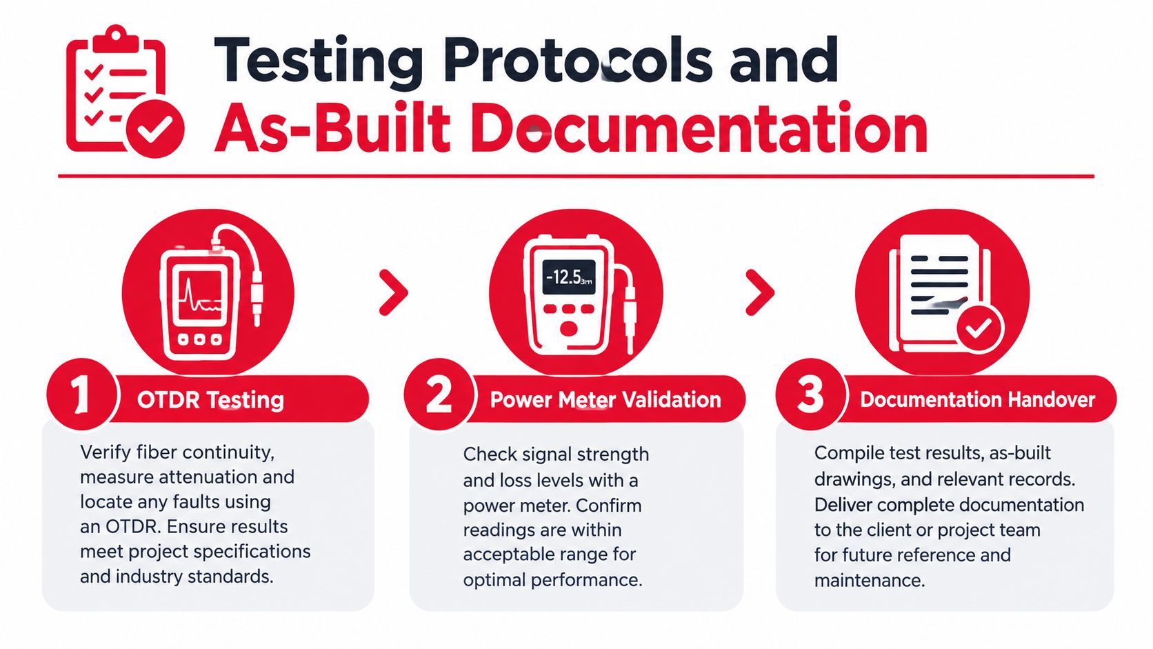
Test the fiber, not just the link light
OTDR testing helps identify event locations, splice behavior, reflections, and unexpected loss along a fiber path. Power-meter validation confirms end-to-end insertion loss against the design allowance. Both tests serve different purposes, and neither should be treated as a substitute for the other.
Test conditions must be controlled and recorded. Document launch and receive equipment, test direction, wavelength, fiber identification, test date, technician, and acceptance threshold. Clean connectors before testing, use appropriate reference procedures, and investigate anomalies rather than averaging them away.
A useful acceptance package includes:
- OTDR traces: Store native files and readable reports for each tested fiber.
- Power results: Record measured loss and compare it with the engineered budget.
- Splice records: Tie closures, trays, ports, and splice positions to route identifiers.
- Exception log: Track failed tests, repairs, retests, and final disposition.
- Equipment records: Capture serial numbers, installed locations, and configuration ownership.
Make documentation operational
As-built GIS records should show the plant that crews can find. Include cable routes, slack loops, handholes, closures, cabinets, splitters, poles, ducts, building entries, splice points, and serviceable endpoints. Use consistent naming across GIS, network management, inventory, and maintenance systems.
The record should also preserve design intent. Note feeder and distribution relationships, spare fibers, occupied ports, split locations, route ownership, easements, and access constraints. A map that shows only a line on a road is not enough for emergency restoration.
Verify service-level obligations before handover
Test the complete service path where the contract requires it. Confirm optical levels, failover behavior, route alarms, management reachability, and application-facing performance against the agreed service definition. If the build can't demonstrate the promised operating state before acceptance, the owner inherits uncertainty along with the plant.
Handover standard: If a future technician can't locate, test, and isolate the asset from the records, the records aren't complete.
Navigating Regulatory and Permitting Steps
Permitting is an engineering dependency, not an administrative afterthought. A broadband route can be technically sound and commercially attractive yet remain stalled because the project lacks a right-of-way agreement, pole-attachment approval, environmental clearance, traffic-control plan, or property easement.
Build a permit matrix by route segment
Break the route into permit units and identify the authority, submission requirements, review sequence, dependency, and construction restriction for each unit. Public right-of-way, private property, utility poles, rail corridors, waterways, historic areas, and environmental zones often follow different processes.
This matrix should live beside the design, not in a separate project-management file. When a route changes, the team needs to know which drawings, applications, traffic plans, and cost assumptions also change.
Treat make-ready and restoration as schedule drivers
Pole attachments can require structural analysis, rearrangement, replacement, grounding, and coordination with multiple owners. Trenching and boring can trigger traffic controls, pavement restoration, utility coordination, and inspection requirements. Historic-preservation or environmental reviews can require route changes before construction begins.
These soft costs are real project costs. Include field surveys, permit drawings, legal review, utility coordination, inspection support, restoration, and post-construction closeout in the funding plan. Underestimating them doesn't make the project cheaper. It moves the shortfall into change orders or delays.
Keep compliance records usable
Maintain approved drawings, permit conditions, easements, pole data, inspection results, restoration evidence, and correspondence in a controlled project repository. Field supervisors should know which conditions affect construction methods, working hours, traffic control, environmental protection, and restoration standards.
Asset retirement also belongs in the operating plan. When old electronics or removed infrastructure leave a site, use a documented chain of custody and an appropriate secure data destruction service in Atlanta where retired equipment may contain sensitive information.
A realistic deployment schedule has separate gates for design approval, access rights, make-ready completion, environmental or historic review, construction release, inspection, and closeout. Combining all approvals into one optimistic milestone hides the dependencies that usually control the field start date.
Strategic Planning and Deployment Frameworks
Fiber has become the default foundation for modern fixed access, but that doesn't mean every project should be planned as a simple FTTH expansion. FTTH and FTTB connections represented 72.68% of fixed broadband subscriptions worldwide in Q2 2025, and global FTTH and FTTB deployment reached 1.8 billion homes passed in 2023, according to global fiber broadband statistics from Point Topic data. Those figures show the scale of fiber adoption, not a universal answer for split ratios, transport topology, or construction method.
The strategic decision is how to use fiber as part of a complete system. A rural cooperative, a municipal network, a regional ISP, and a hyperscale campus may all use fiber, yet they face different route, power, service, interconnection, and maintenance requirements.
Start with service obligations
Write the service objectives before selecting equipment. Separate residential, enterprise, public safety, healthcare, education, wireless, and data center requirements. Define acceptable failure behavior, restoration expectations, latency sensitivity, monitoring needs, and expansion triggers.
Then map the service path from endpoint to application. Identify where traffic aggregates, where it leaves the local network, and which physical corridors carry the largest consequence if they fail. This prevents the access design from becoming disconnected from the services it must support.
Use a decision sequence that exposes trade-offs
- Define the footprint. Record premises, buildings, business clusters, public facilities, wireless sites, and likely growth areas.
- Model application demand. Include device density, streaming, telehealth, cloud use, enterprise traffic, and emerging AI or immersive applications rather than relying on a diluted household average.
- Select the access architecture. Compare PON, Active Ethernet, FTTH, and FTTB according to density, optical budget, field power, service control, and maintenance capability.
- Engineer the middle mile. Select aggregation sites, route paths, interconnection points, protection paths, and regeneration locations.
- Validate physical feasibility. Complete field surveys, pole loading, duct checks, cabinet assessments, power reviews, thermal analysis, and access verification.
- Secure approvals. Align right-of-way, easements, pole attachments, environmental reviews, traffic controls, and restoration requirements with the construction schedule.
- Define acceptance. Establish OTDR, insertion-loss, equipment, failover, GIS, inventory, and service-level deliverables before issuing the construction package.
- Plan operations. Assign ownership for alarms, spares, restoration, documentation updates, maintenance access, and future capacity upgrades.
Measure partners by handoff quality
A design partner should deliver more than route drawings. Review how the partner handles field verification, permit changes, bill of materials, splice engineering, construction redlines, test evidence, GIS synchronization, and exception management. Ask who owns discrepancies between the design model and the installed plant.
Construction capability matters just as much. Fiber installation, make-ready work, splicing, testing, cabinet fit-out, and restoration should follow one accountable quality process, even when multiple subcontractors participate. Data center and cloud-facing projects need the same discipline, with added attention to structured cabling, power coordination, access controls, and commissioning.
Design resilience where it is affordable
Resilience is easiest to add while ducts, poles, cabinets, and route crossings are being built. Consider spare fibers, diverse entry paths, protected aggregation, alternate power, maintainable closures, and equipment space where the service impact justifies the investment. Don't add redundant logic to a physically shared corridor and call the result diverse.
A strong broadband network design leaves room for operational change. It preserves optical margin, documents every asset, supports clear fault isolation, and makes future transport upgrades possible without rebuilding the outside plant. That is the difference between a network that merely reaches customers and one that can support them as applications, traffic patterns, and service commitments evolve.
Southern Tier Resources provides end-to-end engineering, construction, maintenance, fiber splicing, testing, and documentation for wireline and wireless infrastructure, including broadband builds and data center fit-outs. If you're planning a resilient broadband network design from permitting through operational handoff, visit Southern Tier Resources to discuss the physical and deployment requirements with an infrastructure partner.