Data centers consumed around 415 TWh of electricity in 2024, equal to about 1.5% of global electricity consumption, according to the International Energy Agency data cited in the backup power market overview. That scale changes the way engineers should think about data center power backup. It isn't idle insurance sitting in a plant room. It is a live infrastructure system that must detect faults, carry the load, transfer safely, run for as long as fuel and maintenance plans allow, and return to utility power without creating a second outage.
The hidden risk is rarely the nameplate capacity of a generator. Failures occur at the handoff points, inside battery strings, across transfer controls, during maintenance, or when operators discover that a theoretical runtime doesn't match the facility's actual load. A resilient design therefore treats the entire chain, from utility service to rack-level power distribution, as one engineered system.
The Reality of Modern Power Resilience
In the United States, data centers used approximately 176 TWh of electricity in 2023, equivalent to about 4.4% of annual U.S. electricity consumption. That scale makes backup power a core engineering discipline, not a secondary facilities concern. The layered approach described in the IEA-backed market overview combines UPS batteries and generators, but the equipment list alone says little about whether a site will survive a real interruption.
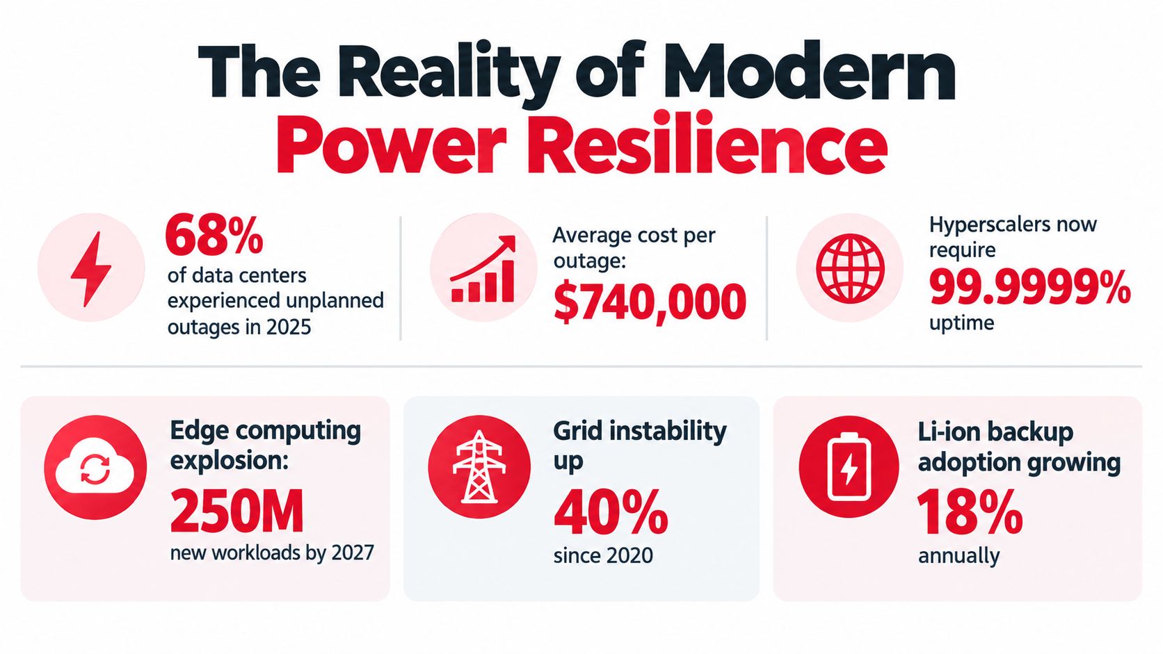
A July 2025 resiliency survey found that 28% of data center operators had experienced a serious power-related outage during the previous three years. Among respondents who avoided one, 71% credited redundant power systems. The survey also reported that 65% had used backup emergency generators during the previous year during a disruption or instability event. The implication is practical: backup generation must be exercised, monitored, and maintained as an operating system. It cannot remain equipment that staff inspect only after a major failure. These figures appear in the Caterpillar data center power systems reference.
Design for the failure you can't see
Generator capacity is easy to compare on a specification sheet. Reliability depends on the less visible chain around it, including sensing thresholds, transfer-switch mechanics, battery health, fuel delivery, cooling, controls, and maintenance procedures. A generator that starts successfully can still fail the load if the switchgear does not transfer, the UPS reaches its runtime limit, or a shared control path loses power.
Validate the sequence with four questions:
- Detection: Does the system identify voltage, frequency, phase, and power-quality faults without nuisance transfers?
- Ride-through: Can the UPS carry the critical load while generators start, stabilize, and accept it?
- Isolation: Can technicians remove a failed component without interrupting the protected path?
- Recovery: Can operators return to utility power without an uncontrolled retransfer?
Practical rule: Redundancy counts only when each layer can be tested, maintained, and isolated without exposing the IT load to a hidden single failure.
Facility events should also be correlated with infrastructure reliability metrics for SREs. Power interruptions, transfer-test failures, and recovery time belong alongside service health and dependency incidents. Application uptime cannot offset a power train that fails during a routine test.
Anatomy of the Backup Power Chain
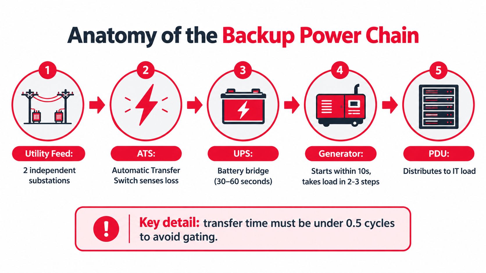
A data center backup system succeeds only when every handoff occurs within its electrical and mechanical limits. Equipment ratings matter, but outage survival depends just as much on sensing, controls, transfer timing, battery condition, fuel, cooling, and downstream distribution.
From utility service to protected load
The utility feed normally supplies the facility. Multiple utility sources or substations can improve resilience only when they remain independent through switchgear, protection, physical routing, and upstream utility equipment. Two feeds sharing a vulnerable path provide less protection than their labels suggest.
The automatic transfer switch, or ATS, monitors the preferred source and controls the change to an alternate source. In a generator-backed design, it detects a qualifying failure, sends the start signal, waits for acceptable generator voltage and frequency, and then transfers the load. Incorrect sensing thresholds can trigger nuisance starts. A slow mechanism, worn contacts, or failed controls can turn a short disturbance into an outage.
The UPS carries the immediate gap. It supplies conditioned power when utility voltage falls outside the permitted range, allowing the generator to start, stabilize, and accept load. Its batteries must support that bridge for the specified duration, while its controls and bypass path must remain available during faults and maintenance.
The generator supplies sustained energy after acceptance. Starting the engine is only the first step. Fuel delivery, cooling, exhaust, controls, paralleling equipment, and load-bank results determine whether it can carry the expected load throughout the event.
Finally, switchboards, distribution panels, remote power panels, and rack PDUs deliver power to IT equipment. A failed breaker, panel, cable, or PDU can interrupt one rack even when the upstream generator and UPS plant operate correctly.
Where the handoff fails
Uptime Institute's survey summary identified power-related service outages most often as UPS failures at 42%, followed by transfer switch failures at 36% and generator failures at 28%. The figures are reported in the Uptime Institute outage analysis.
That pattern directs maintenance toward battery condition, static switches, ATS controls, and transfer testing before adding another generator. Teams evaluating equipment, service coverage, and installation requirements can also find commercial power backup.
Commissioning must prove the complete path under realistic load. Start the engine, verify ATS transfer, confirm UPS ride-through, check protection coordination, and test retransfer behavior. An engine-start test alone leaves the most failure-prone handoffs unverified.
Evaluating UPS Topologies and Battery Tech
UPS selection begins with the quality of power the load needs, not with battery chemistry. A double-conversion UPS rectifies incoming AC to DC and then inverts it back to AC continuously. That architecture provides strong conditioning and isolates the IT load from many utility disturbances, but it adds conversion equipment, heat, controls, and maintenance requirements.
A line-interactive UPS regulates voltage while allowing the load to remain connected to the utility under normal conditions. It can be efficient for less demanding applications, but it generally offers less complete isolation than double conversion. An offline or standby UPS transfers the load to an inverter when utility power fails. That can suit noncritical equipment, but the transfer behavior and conditioning limits make it a poor default for a high-consequence data center load.
Battery chemistry changes the maintenance model
Traditional VRLA lead-acid batteries remain familiar to facility teams. They have established service practices and a broad installed base, but they occupy substantial space and weight, require environmental control, and need disciplined inspection and replacement planning.
Lithium-ion batteries can reduce footprint and often support longer service life, but they introduce different requirements for monitoring, thermal management, fire protection, and end-of-life handling. A lithium installation isn't a simple drop-in replacement for a VRLA room. Operators should involve fire-protection specialists early and use a practical industrial battery fire guide when reviewing suppression, detection, separation, and emergency-response requirements.
| Feature | VRLA (Lead-Acid) | Lithium-Ion (Li-ion) |
|---|---|---|
| Space and weight | Larger and heavier battery rooms are common | More compact installations are possible |
| Monitoring | String and cell monitoring remain important | Battery-management-system visibility is critical |
| Thermal considerations | Heat shortens useful life | Thermal management and fire-risk controls require careful design |
| Maintenance | Familiar inspection and replacement routines | More specialized controls and service expertise |
| Best fit | Established facilities with suitable battery space and maintenance processes | Sites prioritizing footprint, monitoring, and lifecycle flexibility |
Topology and chemistry must match operations
A high-quality UPS topology can't rescue poor battery maintenance. Teams should trend cell voltage, temperature, impedance or equivalent health indicators, alarm history, discharge performance, and environmental conditions. They should also test the complete battery-to-generator sequence instead of treating a healthy-looking dashboard as proof of available ride-through.
BESS architecture can extend beyond traditional UPS duty and may support broader facility or grid functions. That flexibility increases control complexity, however. Critical energy must remain reserved for failover, and any economic dispatch strategy must be subordinate to the protected load's availability requirements.
Generator Sizing and the Critical Handoff
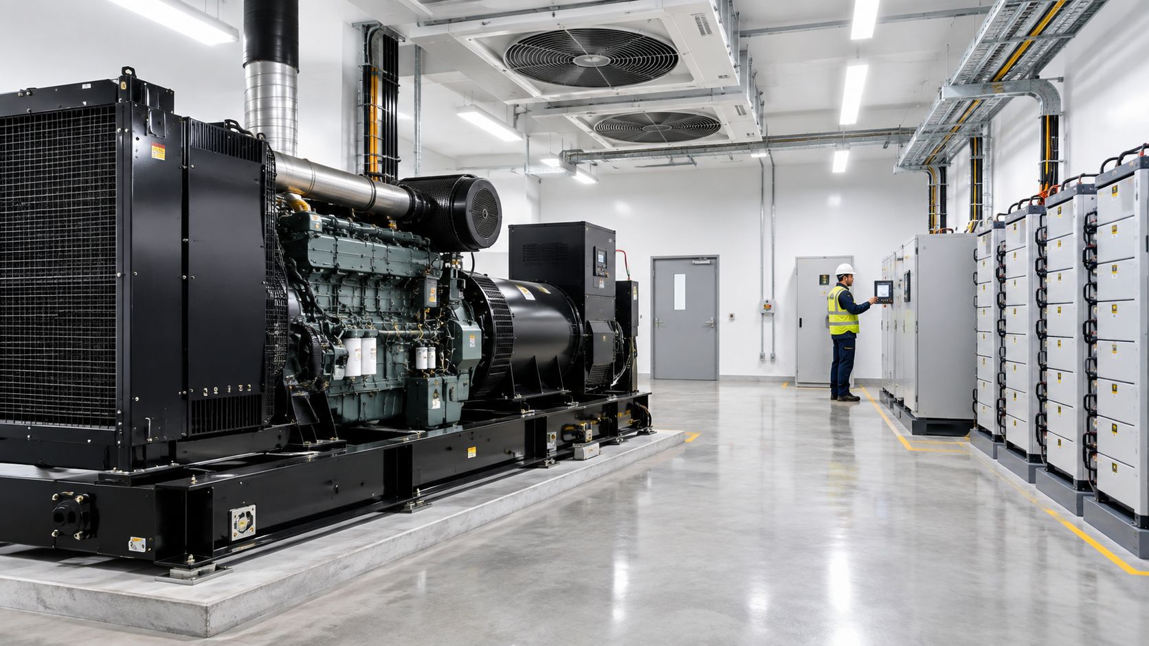
Generators carry the facility after the UPS bridge ends, but their rating must reflect the complete operating load. Include IT equipment, cooling, pumps, controls, required lighting, battery chargers, and every system needed to keep the data hall stable. A calculation based only on server nameplates can leave the plant unable to accept the actual step load.
Size for transitions, not just steady state
Dense compute clusters and cooling equipment can change demand quickly. Model motor starting, variable-frequency-drive behavior, harmonic current, transformer energization, power factor, nonlinear UPS input, and staged load pickup. Paralleling controls also need a defined sequence. Priority loads should connect first, while less critical loads wait until voltage and frequency have settled.
A typical handoff follows four stages:
- The UPS carries the protected load when utility power moves outside acceptable limits.
- The generator starts and stabilizes before accepting load. Engine speed and voltage must reach their operating limits first.
- The ATS or paralleling switchgear transfers in controlled stages, avoiding a collapse from an excessive instantaneous step.
- The control system confirms stable operation, tracks alarms, and keeps the load on the available source until utility quality is verified.
The transfer path can fail even when the generator itself is healthy. Test sensing thresholds, start delays, breaker interlocks, synchronization, staged transfer, bypass paths, retransfer timing, and response to failed components. One successful commissioning transfer does not prove outage readiness. Recurring tests under representative load, along with documented restoration procedures, expose problems that a dashboard may not show.
Fuel is part of the electrical design
Tier III facilities commonly maintain at least 72 hours of onsite fuel, according to the data center generator backup power benchmark. Actual endurance also depends on fuel quality, tank configuration, filtration, delivery access, replenishment contracts, and local restrictions. A nominal tank duration provides little protection if suppliers cannot reach the site during a regional emergency or contaminated fuel prevents reliable engine operation.
Generator capacity should also support future load growth and maintenance conditions. A plant that works only with every set available has theoretical redundancy, not practical resilience. Confirm that the remaining sets can carry the required priority load while one unit is offline, and verify that fuel systems, switchgear, controls, and cooling support the same operating scenario.
Caterpillar's historical account of a data center installation describes an original plant with four Cat D399 generator sets, a fifth added in the early 1980s, and a later bank of three Cat 3516 generators added in the late 1980s. The example shows how generator plants expand as computing demand and resilience requirements grow, rather than remaining fixed after the initial build.
A useful visual reference for generator operation and maintenance can be placed here, after the design and fuel considerations:
The Battery Duration Myth in the AI Era
More battery runtime does not automatically improve outage survival. Most data center UPS systems provide roughly 5 to 15 minutes of full-load runtime, and 5 to 10 minutes is often enough for generator start-up and automatic transfer sequencing. The battery's primary job is ride-through while the standby source becomes available, not sustaining a prolonged outage.
That distinction exposes a common design error. Extending autonomy adds battery cells, floor loading, cooling demand, monitoring points, replacement work, and fire-protection requirements. If the generator can start and accept load within the planned bridge interval, extra battery capacity may deliver less resilience per dollar than better controls, transfer-switch testing, generator redundancy, and fuel logistics.
Runtime also has to be validated at the load served. Nameplate capacity can hide aging cells, temperature effects, battery-string imbalance, inverter limits, and a UPS operating near its maximum rating. A test that measures only static runtime will not prove that the system survives the transfer sequence, load step, or a second failure during recharge.
AI raises the consequence of a bad assumption
AI workloads increase power density and make power-quality behavior harder to predict. A 2026 survey found that 57% of respondents cited those pressures as a major impact on power and energy storage needs, according to the coverage of the hyperscale backup generator market. Battery sizing should therefore use measured or validated load profiles, including transient demand, rather than a generic rack assumption.
The same source projects the data center battery market rising from USD 4.82 billion in 2026 to USD 10.23 billion by 2032. That forecast shows increasing investment, not proof that batteries can replace long-duration generation economically. Separate the applications:
- UPS bridge duty: Conditioned power until a generator or restored utility source takes over.
- Short-duration storage: Support for brief disruptions or controlled operating strategies.
- Long-duration backup: Sustained energy during an extended grid failure.
Batteries perform well in the first use case and can support the second in bounded designs. The third remains difficult at large critical facilities because duration, footprint, recharge requirements, and cost scale together.
Grid interaction needs hard boundaries
Data centers are also becoming major behind-the-meter storage participants. In the first half of 2026, they represented around 75% of behind-the-meter storage installations, with the share expected to reach around 90% by 2030, according to Latitude Media's battery storage analysis. Demand response, grid services, and renewable smoothing can improve economics, but dispatch controls must reserve the energy required for mission-critical failover.
That reserve needs a defined state-of-charge floor, tested alarms, and an operating rule that overrides commercial dispatch during utility instability. Without those controls, a battery can be available on paper yet depleted when the transfer chain needs it.
Mapping Redundancy Levels to Uptime SLAs
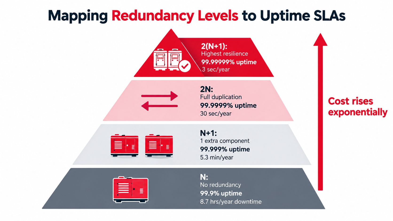
Redundancy is a relationship between capacity, topology, maintainability, and operating discipline. N means the facility has only the capacity required for the intended load. N+1 adds one extra component, such as a generator, UPS module, or cooling unit. 2N duplicates the entire capacity path, allowing one complete path to support the load while the other is unavailable. 2(N+1) combines duplicated paths with spare capacity inside each path.
Choose the architecture by failure scenario
The right model depends on the SLA, the workload, the maintenance window, and the consequences of a service interruption. A single enterprise facility may accept N+1 if its business can tolerate planned maintenance and controlled risk. A colocation provider serving multiple customers may need independent distribution paths so one customer's maintenance activity doesn't expose another customer's load.
The architectural choice should answer four questions:
| Decision question | What to verify |
|---|---|
| Can one component fail? | Confirm that remaining capacity supports the complete critical load |
| Can maintenance occur online? | Test isolation, bypass, breaker coordination, and work procedures |
| Can one distribution path fail? | Validate dual-corded equipment, A and B feeds, and rack-level separation |
| Can operators control the system under stress? | Review alarms, switching authority, procedures, and incident training |
N+1 protects against a component failure, but it can still fail if the common bus, control system, fuel system, or distribution path remains shared. 2N provides stronger path separation, yet duplicated equipment can introduce complexity, synchronization challenges, and more maintenance points. Overbuilding without disciplined commissioning can create a larger system that operators understand less well.
SLA language must match physical capability
An availability promise should reflect the complete power path, not only the generator count. A facility may advertise dual utility sources, but if both sources terminate in a shared switchboard, the design still has a common failure point. Likewise, two UPS modules don't create 2N resilience if both depend on one battery system, one static bypass, or one poorly maintained transfer control.
Reliability is a property of the path, not the equipment list.
Map the SLA to credible failure tests. Can the site lose a generator during peak load? Can technicians isolate a UPS module without dropping either distribution path? Can an ATS fail in the expected position while the alternate path remains available? Can the team complete these actions under documented procedures rather than relying on an experienced individual's memory?
Executing Turnkey Infrastructure Fit-Outs
Power backup fails in the gaps between scopes. The electrical contractor may install the generator and ATS, the controls vendor may configure sequencing, the cabling team may build the distribution network, and the commissioning agent may discover that nobody owns the complete failure path. Each handoff creates a chance for mismatched assumptions about load schedules, labeling, alarm points, clearances, testing, or as-built documentation.
A turnkey infrastructure partner reduces that fragmentation by coordinating power, connectivity, structured cabling, and installation sequencing under one accountable plan. That doesn't eliminate the need for specialist manufacturers or independent verification. It does make ownership clearer when a transfer test exposes a problem between switchgear controls and the monitoring network.
What execution quality looks like
A serious fit-out partner should contribute during design, not arrive only after equipment has been purchased. The review should include:
- Design coordination: Align electrical one-lines, equipment layouts, cabling routes, grounding, controls, and maintenance access.
- Permitting and field readiness: Resolve authority requirements, safety planning, delivery constraints, and construction sequencing before mobilization.
- Installation discipline: Use qualified crews for power infrastructure, fiber pathways, structured cabling, terminations, labeling, and physical separation.
- Testing and commissioning: Verify continuity, insulation, controls, alarms, transfer behavior, fiber performance, and integrated operation under the approved test plan.
- Documentation: Deliver accurate as-built drawings, test records, asset information, and maintenance references that match the installed plant.
The final deliverable isn't a room full of equipment. It is a facility that operators can understand, maintain, test, and restore without guessing. That requires clean labeling, accessible isolation points, current drawings, clear escalation paths, and a safety culture that treats energized work and switching procedures as engineered activities.
Southern Tier Resources describes end-to-end telecom infrastructure work that includes fiber-optic construction, splicing, testing, documentation, wireless infrastructure, and data center fit-outs. Its infrastructure services can be evaluated alongside electrical, controls, and commissioning specialists when a project needs coordinated delivery across power and network systems.
Southern Tier Resources supports data center fit-outs by integrating power, connectivity, and structured cabling with engineering, construction, testing, and as-built documentation. Visit Southern Tier Resources to discuss a coordinated infrastructure plan that closes handoff gaps and prepares your facility for reliable operation from day one.