The splice trailer is parked beside a fresh trench, the closure is open, and the crew is working around wind, dust, traffic, and a deadline. One fiber has already been stripped, another is waiting in the cleaver, and the fusion splicer is displaying a loss estimate that looks good enough to accept. That number is useful, but it isn't the acceptance decision. A reliable fiber optics splicing program depends on controlled preparation, skilled judgment, measured link performance, and records another crew can trust.
Fiber splicing became commercially important during the first deployment wave of optical telecommunications in the 1970s. Bell Labs reported optical fiber attenuation below 2 dB per kilometer by 1974, and a January 1976 Atlanta digital-transmission experiment operated at 44.736 Mb/s over a cable containing 144 fibers, with fiber joining and splicing among the issues under examination in the field trial (Bell Labs Technical Journal). The tools have improved since then, but the field requirement hasn't changed: every joint must preserve optical power and remain defensible when the link is tested, commissioned, repaired, or upgraded.
What a Splicer Actually Does in the Field
At the roadside, a good splicer controls the job before touching the machine. The trailer door stays shut against gusts, the work surface is clean, the battery and power supply are stable, and the fibers are identified against the splice plan. A rushed operator may get an arc and a displayed estimate, but an experienced technician controls the conditions that make the arc repeatable.
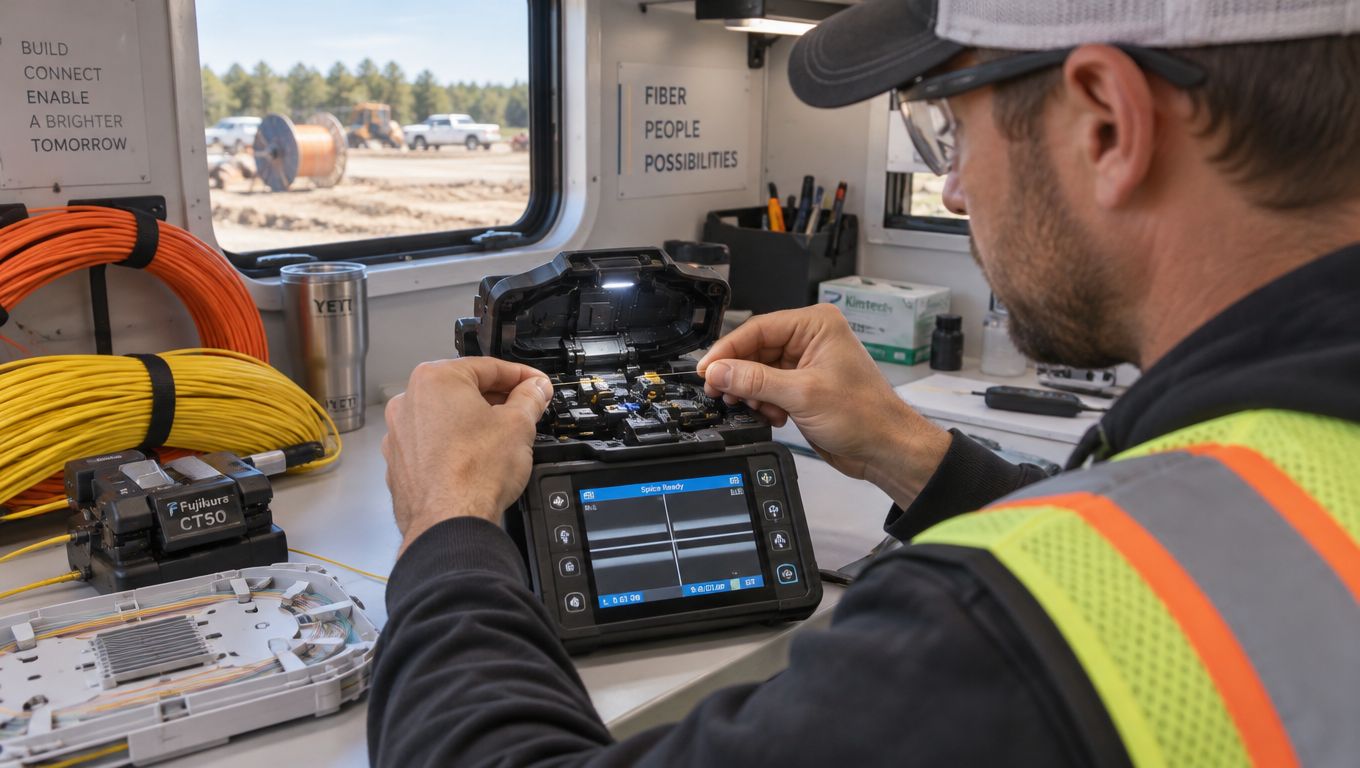
A single joint involves more decisions than most project schedules acknowledge. The technician must stabilize the work area, strip the coating without nicking the glass, clean the bare fiber, inspect the end, cleave it accurately, and confirm that the fiber types and mode-field characteristics are compatible. Only then does the splicer align and fuse the ends. Afterward, the technician proof-tests the joint, installs protection, routes the fiber in the tray, and records its position.
Field rule: The machine performs the arc. The technician creates the conditions that allow the machine to produce a reliable joint.
Fusion splicing permanently joins prepared glass with an electric arc. It normally suits backbone, access, data-center, and other installations where low loss, mechanical stability, and repeatability matter. Mechanical splicing aligns fiber ends inside a fixture, generally with an index-matching medium, and can be useful for temporary restoration, testing, or a small repair where deploying a fusion splicer isn't practical. The choice isn't only about equipment price. It affects the link budget, protection method, testing burden, and future maintenance.
The optical loss budget is the true yardstick. A splicer's screen estimates loss from images and alignment data, but it doesn't measure the complete installed path. Connectors, cable attenuation, bends, splitters, and every other joint consume margin. A clean-looking splice can still sit inside a link that fails end-to-end insertion-loss acceptance.
Fusion Versus Mechanical Splicing
Fusion is the normal choice for a permanent network because it creates a stable glass-to-glass joint with low optical discontinuity. Mechanical splicing earns its place when speed, portability, or emergency restoration matters more than the lowest possible loss. Neither method should be selected without considering the route's loss budget and the required return-loss performance.
ITU-T Recommendation L.12 provides a useful benchmark for fusion work. For trunking routes, it recommends an average single fusion-splice loss of no more than 0.1 dB, with 95% of measured splices at or below 0.5 dB. For access networks, it lists a typical average of 0.2 dB and a maximum of 0.8 dB for 95% of samples. The recommendation also identifies a grade V return-loss requirement of at least 55 dB.
| Criterion | Fusion Splicing | Mechanical Splicing |
|---|---|---|
| Optical performance | Designed for very low loss when preparation and alignment are controlled | Usually accepts more interface-related uncertainty |
| Permanence | Permanent glass joint, protected in a sleeve and closure | Retained by a mechanical alignment body, suitable for selected temporary or repair uses |
| Return-loss control | Strong choice where reflection must be tightly controlled | Interface and matching medium require closer application review |
| Equipment | Requires a calibrated fusion splicer, cleaver, heater, and trained operator | Requires mechanical splice hardware and preparation tools, without an arc splicer |
| Best use | Trunk, access, data-center, backbone, and long-life infrastructure | Emergency restoration, temporary service, testing, or constrained small repairs |
| Main trade-off | Higher equipment and training commitment | Faster deployment, but potentially less optical and mechanical margin |
The standard doesn't give permission to accept every fusion joint that looks neat. It gives the crew a performance framework. A trunk route with many joints has little tolerance for careless outliers, while a short access repair may allow a different decision if the complete measured link remains within budget.
Mechanical splicing can be the right operational answer during an outage when a restoration crew needs to re-establish service before permanent construction is possible. It becomes a poor default when a contractor uses it to avoid planning, training, or the capital cost of the correct fusion equipment. The decision should be documented, tested, and revisited if the temporary repair becomes part of the permanent route.
Tools, Materials, and Site Preparation
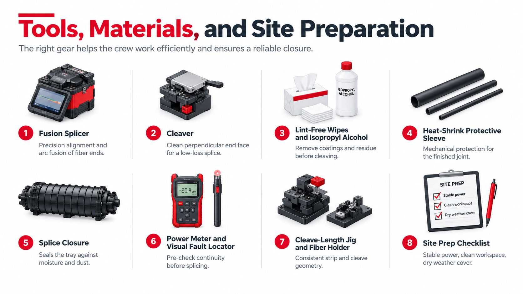
Preparation starts before the closure opens. A crew should have the correct fusion splicer and program, a precision cleaver, compatible fiber holders, strippers, lint-free wipes, suitable cleaning alcohol, heat-shrink sleeves, a sleeve heater, splice trays, closure hardware, identification materials, and test equipment. Keep a fiber waste container within reach. Bare glass fragments don't belong on the work surface, truck floor, or clothing.
Control the work area first
Corning's single-mode fusion-splicing procedure begins with controlling dust, precipitation, and wind, then stripping, cleaning, inspecting, and precision-cleaving the fiber. That order matters. The splicer can't compensate for dirt carried into the arc chamber or an end face damaged by a poor cleave.
Use a trailer, tent, or other suitable enclosure when conditions are unstable. Keep the work surface organized so cleaned fibers don't cross with stripped fibers, and don't allow an open alcohol bottle, loose coating scraps, or cut glass to share the immediate splice area.
Prepare each fiber deliberately
Strip only the length required by the holder and sleeve design. Clean the exposed glass with a lint-free wipe and appropriate alcohol, using a consistent motion rather than dragging contamination back across the fiber. Inspect the end face, then cleave immediately so airborne particles have less opportunity to settle.
A good preflight looks like this:
- Power and environment: Confirm stable power, a charged battery, dry working conditions, and protection from wind and precipitation.
- Fiber identity: Match tube, ribbon, buffer, and fiber markings to the splice map before cutting.
- Tool condition: Clean the V-grooves, check the cleaver, verify holders, and confirm the splicer program matches the fiber.
- Consumables: Stage sleeves, wipes, alcohol, labels, tray hardware, and waste containers before the first splice.
- Test plan: Confirm wavelengths, reference settings, launch and receive fibers, and the acceptance record required by the project.
The avoidable failures are usually ordinary. A dirty cleaver, a coating fragment in the V-groove, a damp workspace, or a fiber that was touched after cleaning can create bubbles, core distortion, alignment errors, or excessive loss. Site preparation isn't administrative overhead. It is the first quality-control step.
Running the Fusion Cycle and Protecting the Joint
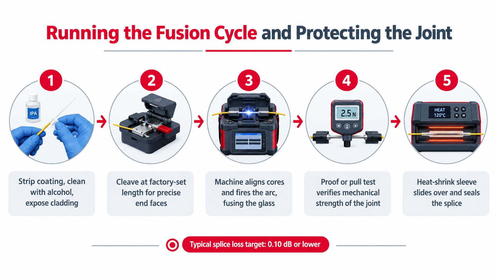
The active fusion cycle is short, but the decisions around it determine whether the joint deserves acceptance. Slide the heat-shrink sleeve onto one fiber before loading the pair. Confirm that both fibers are the same type and are being prepared with the correct holder and mode-field settings.
Load, inspect, and fuse
Place each cleaved fiber in its V-groove without allowing the end face or bare glass to contact the bench. Close the wind protector, run the machine's inspection and alignment cycle, and watch the image rather than treating the automated sequence as a substitute for judgment.
Reject a fiber if the cleave is visibly chipped, angled, cracked, contaminated, or inconsistent with the holder geometry. Re-strip, re-clean, and re-cleave it. Repeating a poor setup won't make the next arc reliable.
The machine estimates splice loss from alignment and image data. That estimate helps identify an obviously bad joint, but it isn't an optical acceptance measurement. For planning, the FOA-referenced practical allowance is approximately 0.15 dB per single-mode fusion splice, even though homogeneous, well-executed joints can be substantially lower. Use the allowance conservatively in the design, then verify the installed link with test equipment.
Prove and protect the joint
Run the splicer's programmed proof or pull test when the equipment provides one. A joint that looks smooth may still have a mechanical weakness caused by contamination, poor arc conditions, or damaged glass. If the machine flags an issue, don't hide it by moving directly to the sleeve.
Center the heat-shrink sleeve over the splice and place it in the heater according to the sleeve and equipment instructions. Let it cool without bending the fiber sharply. Inspect the finished sleeve for even contraction, exposed bare fiber, cracks, or displacement. Then route the protected joint into the tray without twisting, crossing, or placing stress on the splice.
The displayed loss is a screening signal, not a sign-off. A technician accepts the joint only after preparation, protection, and measured link testing support the decision.
Watch this practical demonstration of the fusion workflow, but apply the project procedure and equipment instructions rather than copying settings blindly.
Acceptance Testing With OTDR and Power Meters
A clean OTDR event doesn't automatically mean the link passes. Insertion-loss testing and OTDR characterization answer different questions, and treating them as interchangeable is one of the fastest ways to create false acceptance.
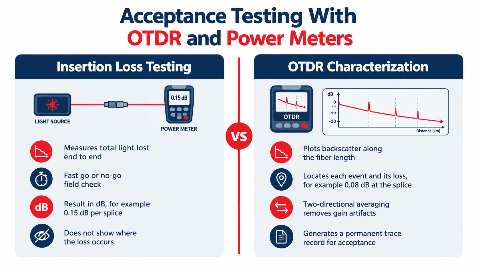
An optical loss test set, or a light source and power meter, measures the total loss from one end of the link to the other. It tells the acceptance team whether the installed path remains inside the optical power budget, but it doesn't identify which splice or connector consumed the margin.
An OTDR sends pulses into the fiber and plots backscatter and reflective events along its length. That makes it valuable for locating a high-loss splice, a connector problem, a bend, or a closure issue. It also introduces interpretation risk, especially when the two fibers have different backscatter characteristics.
Why one direction isn't enough
Corning's OTDR guidance reports that, for homogeneous single-mode splices, unidirectional OTDR estimates fall within ±0.05 dB of actual loss in only 54% of cases, within ±0.10 dB in 78%, and within ±0.20 dB in 97%. Dissimilar fiber designs and mode-field diameters can increase uncertainty.
That is why the crew should use launch and receive fibers, select a pulse width appropriate to the link, average the trace, and test from both directions. Average the corresponding event results rather than accepting the better-looking one-way trace. A one-way event can appear as a false gain or an exaggerated loss because the OTDR compares backscatter conditions on either side of the splice.
Reconcile the evidence
Use this sequence at acceptance:
- Inspect and clean connectors before establishing the reference.
- Set the instrument correctly, including wavelength, refractive index, pulse width, range, and averaging.
- Acquire OTDR traces from both directions with launch and receive fibers attached.
- Average the matching splice events and investigate asymmetric readings.
- Run end-to-end insertion-loss testing in the required directions and compare the result with the actual link budget.
- Document exceptions, including a re-splice, corrected test setting, unusual reflection, or unresolved margin issue.
The OTDR trace is an important diagnostic record, not a replacement for end-to-end qualification. If a splice shows a high one-way event but the bidirectional average and insertion-loss result are acceptable, check the settings and fiber differences before cutting the joint. If the link loss exceeds budget, don't let a low displayed event override the failed end-to-end result.
Crew Design, Training, and Quality Control
A fusion splicer is only one production resource. The larger constraint is often the crew system around it, including preparation, fiber identification, closure work, testing, rework, travel, safety, and records. A machine can increase repeatability, but it can't interpret a suspicious trace, recognize a damaged cleave, or decide whether an outlier should be re-spliced.
A 2025 Fiber Broadband Association white paper estimated that approximately 180,000 additional workers were needed to meet deployment goals driven by BEAD and other federal programs (Fiber Broadband Association white paper). Separately reported FBA data indicates that labor represents about 64% of above-ground fiber-infrastructure cost and 72% of below-ground cost, which makes productivity and rework central financial variables rather than minor field details.
Build the crew around the acceptance cycle
A small operation may combine roles, but the program still needs clear ownership. One technician can perform the splice, another can manage fiber identification and tray organization, and a test lead can protect the acceptance record. On larger builds, separate production and quality functions reduce the temptation to approve a joint only because the crew is behind schedule.
Track the work that causes delays:
- Preparation time: Closure access, cable fixing, fiber identification, and cleaning.
- Splice production: Fusion work completed without rework.
- Test turnaround: Time between closure completion and usable OLTS and OTDR results.
- Rework: Joints cut out because of loss, reflection, protection, routing, or documentation problems.
- Mobilization: Travel and setup time for rural routes, night work, and emergency restoration.
These measures help a manager decide whether the bottleneck is equipment, training, crew balance, site access, or test review. Buying another splicer won't solve a program where fibers arrive unidentified or traces sit unreviewed.
Train for judgment, not button pressing
New technicians need supervised practice with stripping, cleaning, cleaving, machine inspection, sleeve placement, tray routing, and test interpretation. They also need to understand the link budget well enough to challenge a plausible-looking result. Night restoration requires the same discipline under worse visibility, tighter access windows, and greater pressure to return service.
For carriers, ISPs, municipalities, and facility operators, Southern Tier Resources is one example of a telecom infrastructure partner that provides fiber construction, splicing, testing, and documentation services. The practical standard is the same whether work is performed internally or contracted: define competence, review evidence, and make quality ownership explicit before production begins.
Documentation, As-Builts, and Troubleshooting Common Faults
A completed closure without reliable records is only partially complete. The handoff should let another technician identify every fiber path, locate every splice, retrieve the corresponding OTDR trace, and understand why an exception was accepted or rejected.
Record the route, cable identifiers, tube and fiber assignments, closure location, splice-tray position, test wavelengths, insertion-loss results, bidirectional OTDR traces, and any rework. Keep the splice map aligned with the as-built route documentation. Store files using names that survive staff turnover, hardware replacement, and a future restoration call.
Read the symptom before cutting fiber
| Field symptom | First checks | Likely decision |
|---|---|---|
| High loss in one OTDR direction | Compare the reverse trace, review launch and receive fibers, verify settings and averaging | Retest correctly before re-splicing |
| Excessive end-to-end insertion loss | Compare the measured result with the link budget, then isolate events with OTDR | Locate the consuming component, re-splice unacceptable joints |
| Loss changes after closure movement | Inspect tray routing, sleeve seating, bend conditions, and closure strain relief | Correct mechanical stress or microbend conditions |
| Reflective anomaly | Inspect connectors, closure interfaces, damaged fiber ends, and event location | Clean, reconnect, or repair the reflective point |
| Bubbles, distortion, or visible splice irregularity | Recheck cleanliness, cleave quality, and arc conditions | Cut back and prepare a new joint |
A high one-way OTDR event isn't automatically a bad splice, and a low one-way event isn't automatically a good one. The decision should combine bidirectional OTDR evidence, end-to-end loss, the route budget, physical inspection, and documentation quality.
Before signing off, ask four questions: Does the total link loss fit the budget? Are unusual OTDR events explained? Is every splice mapped to the correct fiber and tray position? Can the next crew reproduce the test result? If any answer is no, the closure isn't ready for handoff.
Southern Tier Resources provides end-to-end telecom infrastructure support, including fiber splicing, testing, construction, maintenance, and as-built documentation for carrier, ISP, data-center, and wireless projects. If your program needs disciplined crews and acceptance records that stand up after commissioning, contact Southern Tier Resources to discuss the route, testing scope, and deployment requirements.