At midnight, a crew lead is standing over a splice case with a 144-count backbone, a tight loss budget, and a customer waiting for service to return. The truck carries a fusion splicer, mechanical splice kits, and ribbon equipment, but the fastest method isn't automatically the right method. The choice affects signal margin, restoration time, closure space, and how easily the network can support higher-rate optics later.
A good field decision starts with the fiber count, the environment, the repair objective, and the acceptance criteria. Fusion, mechanical, and ribbon splicing each solve a different problem. The technique that works for a temporary vault restoration may be a poor choice for a buried backbone or a hyperscale data center. This guide gives you a practical selection rule, then shows how to prepare, splice, test, protect, and troubleshoot the finished joint.
Why the Right Fiber Splicing Technique Matters On Site
A splice rarely fails because the glass refuses to join. More often, the problem appears later as accumulated attenuation, unstable readings, a difficult restoration, or a closure that leaves no room for future work. A small loss at one joint becomes important when a route contains many joints, connectors, bends, and repair points.
Fusion splicing became commercially practical in the late 1970s and developed into the dominant low-loss joining method for optical fiber. Sumitomo Electric's technical history records Fujikura's introduction of the first fusion splicer in 1977, followed by Sumitomo's TYPE-3 sales in 1980 for multimode fiber and later equipment for single-mode fiber. The move toward core monitoring mattered because single-mode cores are much smaller than multimode cores, leaving less room for alignment error.
Start with the network consequence
Before you pick up a tool, ask four questions:
- Is this joint permanent? If the cable will remain in an outside-plant closure for years, environmental stability and low loss usually outweigh equipment convenience.
- How many fibers must be joined? A single repair fiber and a high-count ribbon backbone require different workflows.
- What is the restoration constraint? A powered, sheltered splice trailer supports a different decision than a wet vault during an emergency.
- What does the test plan require? The method must meet the project's insertion-loss and return-loss limits, not just produce a joint that looks acceptable.
Fusion splicing is usually the default for permanent backbone, access, and data-center work because the arc creates a continuous glass joint. Mechanical splicing earns its place when speed, portability, or temporary restoration matters more than minimum loss and long-term environmental durability. Ribbon and mass fusion become compelling when labor and closure density dominate the job.
Practical rule: Choose the technique that protects the entire link budget and the next maintenance window, not merely the technique that finishes the current splice first.
The remainder of the decision is straightforward. Use single-fiber fusion for low-loss permanent joints, mechanical splicing for constrained restoration or limited-access work, and ribbon or mass fusion when a high-count cable is designed for parallel processing.
The Core Concept of a Fiber Splice
A fiber splice joins two optical fibers end to end so light can cross the junction with minimal loss and reflection. The simplest mental model is two carefully cleaved glass ends, aligned inside a protective housing. In a fusion splice, the glass becomes one continuous structure. In a mechanical splice, an alignment sleeve or fixture holds the ends in position.
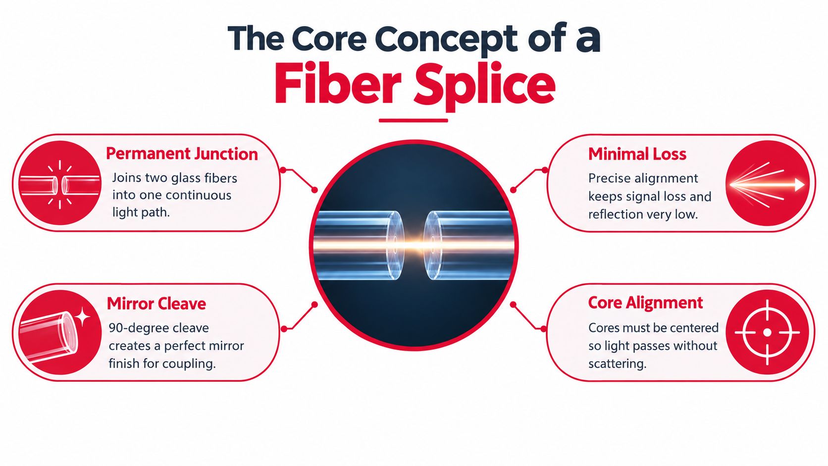
Two measurements govern the quality of the joint.
Insertion loss and return loss
Insertion loss is the optical power that doesn't reach the receiver because the splice scatters, reflects, or otherwise interrupts part of the signal. Return loss describes reflected light traveling back toward the transmitter. High reflection can disturb laser sources and reduce the usable performance margin of a link.
A clean, square cleave gives the two fiber faces the best chance of coupling light. If one end is angled, chipped, contaminated, or offset from the other, the light path no longer passes cleanly through the cores. The receiver sees less power, while the transmitter can see more reflected energy.
The Fiber Optic Association identifies an expected loss of about 0.15 dB for a single-mode fusion splice, while field guidance commonly uses 0.1 dB as a target and 0.3 dB as an upper acceptance ceiling for an individual splice. IEEE-related splice material describes measured means around 0.02 dB for several fiber combinations, with sample maximums in the 0.04 to 0.08 dB range.
Why single-mode needs tighter control
Multimode fiber carries light through a larger core, so small alignment differences may have less effect on coupling. Single-mode fiber has a much smaller core, so lateral offset, angular error, and poor cleave geometry can consume link margin quickly.
The splice isn't judged only by whether it passes a machine's estimated-loss screen. A strong result sits close to the fiber and equipment's intrinsic performance, remains stable during testing, and leaves enough margin for the complete route. That's why cleaning, cleaving, alignment, arc control, and documentation belong to one quality process rather than separate tasks.
Comparing Fusion Mechanical and Ribbon Splicing
The three techniques differ in how they join fibers and how they spend crew time. Fusion uses an electric arc to melt the prepared ends into a continuous glass joint. Mechanical splicing uses a precision sleeve or fixture, often with index-matching gel, to hold the ends together without melting them. Ribbon and mass fusion applies the fusion process to multiple fibers in parallel.
| Attribute | Fusion Splicing | Mechanical Splicing | Ribbon / Mass Fusion |
|---|---|---|---|
| Joining mechanism | Electric arc fuses glass-to-glass | Alignment sleeve or fixture holds fiber ends | Electric arc fuses several ribbon fibers in parallel |
| Typical single-mode loss | About 0.02 to 0.05 dB in modern core-alignment equipment, with field targets around 0.1 dB (ITU-T) | About 0.1 to 0.5 dB (technical comparison) | Depends on equipment, fiber type, preparation, and acceptance specification |
| Return-loss profile | Fusion joints can exceed 60 dB (technical comparison) | Commonly around 40 to 55 dB (technical comparison) | Designed for parallel permanent joints, with performance verified by the project test plan |
| Equipment | Fusion splicer, cleaver, strippers, cleaning supplies, protector oven | Cleaver, strippers, cleaning supplies, mechanical splice assembly | Mass fusion splicer, ribbon holder, ribbon cleaver, ribbon protectors |
| Best fit | Permanent outside plant, carrier, access, and backbone joints | Emergency restoration, constrained access, temporary or limited-scale work | High-count ribbonized backbone and dense data-center builds |
| Main advantage | Lowest practical loss and strong long-term stability | Fast setup without fusion power or arc control | Processes multiple fibers in one operation |
| Main trade-off | Requires calibrated equipment and trained operators | Higher loss and greater environmental sensitivity | Requires ribbon preparation, compatible cable construction, and specialized workflow |
The numbers need context. ITU-T guidance identifies fusion as the most widely used field method for reliable single or mass splices. The arc removes the refractive interface between the fiber ends, while a mechanical splice retains an alignment interface that can be more sensitive to temperature cycling, vibration, and aging.
Ribbon fusion also changes the labor problem. Prysmian's discussion of AI infrastructure and fiber design notes that 12-fiber ribbon mass fusion can be completed in a single process, while emerging high-density terminations are increasing pressure on deployment time and rack space. That doesn't make ribbon equipment universally better. It makes it better when the cable, splice tray, crew skill, and closure design all support parallel work.
How Each Splicing Technique Is Performed Step by Step
A reliable splice follows a repeatable preparation sequence. The equipment changes by method, but the discipline doesn't. Keep the cleaver clean, protect bare glass from contamination, and dispose of fiber shards immediately.
Single-fiber fusion
- Strip the coating. Use the correct fiber stripper to expose clean bare glass without nicking it.
- Clean the glass. Wipe the exposed fiber with a lint-free wipe and suitable cleaning fluid. A contaminated end can produce a poor arc or a visible defect.
- Cleave the fiber. Use a precision cleaver to create a flat, mirror-like end face. The intended geometry is close to 90 degrees to the fiber axis.
- Load the V-grooves. Place both fibers into the fusion splicer's holders. A core-alignment model uses cameras and automated alignment to position the fiber cores.
- Run the arc. Complete the arc test when required, then allow the machine to fuse the ends and display its estimated loss.
- Protect the joint. Slide a heat-shrink splice protector over the joint and place it in the protector oven. After shrinking, route the splice into the tray without introducing a tight bend.
A crew typically carries a stripper, cleaver, wipes, cleaning fluid, fiber holders, fusion splicer, spare electrodes, heat-shrink protectors, and a protector oven. Before the installation window, the broader worksite also needs cable access, safety controls, slack planning, and a clean work area. A practical guide to prepare for fibre installation day can help crews organize those dependencies before splicing begins.
Mechanical splicing
Mechanical work begins with the same stripping, cleaning, and cleaving discipline. The prepared ends enter an alignment sleeve or precision fixture containing index-matching gel. The technician brings the ends together, locks the crimp, cap, or retaining mechanism, and places the finished assembly into its holder.
No arc or protector oven is required. That saves setup time, but the joint still needs careful routing and enclosure protection. The gel and alignment hardware must remain stable, and the splice shouldn't be treated as a permanent fusion joint because it produced a usable reading.
Ribbon and mass fusion
Ribbon work adds fiber organization to every preparation step. The technician exposes the ribbon, fans out the fiber array as required by the holder, removes the coating according to the equipment procedure, cleans each exposed surface, and cleaves the array as one block. The ribbon holder then positions the fibers in the mass fusion splicer, which applies the arc across the aligned group.
After the machine completes the operation, the crew installs a ribbon protector and places the joint in a tray designed for ribbon storage. A 24-fiber cable may require a different holder and preparation process from a 12-fiber ribbon, so don't assume that a single-fiber workflow scales by adding more hands.
The video below shows the physical sequence from preparation through protection.
Testing and Inspecting the Finished Splice
A splice isn't finished when the protector cools. It's finished when the crew can show that the joint meets the project's acceptance criteria and can identify it later from the records. Testing should happen before the closure is sealed, while the technician can still rework the fiber.
Use inspection before measurement
Start with a microscope or video inspection system. A view at 100x or 200x magnification can reveal contamination, chipped glass, a lipped cleave, or a visible core defect before the team relies on an optical reading. Never look directly into a fiber. Confirm that the fiber is dark and follow the site's laser safety procedure.
Next, use a calibrated light source and power meter for insertion-loss testing. A bidirectional test helps identify asymmetric readings caused by launch conditions, fiber differences, or setup errors. Record the test direction, wavelength, reference method, fiber identification, and splice location.
Read the OTDR trace as a field signature
An OTDR trace shows a splice as a step in the backscatter profile. A larger-than-expected downward step suggests excess insertion loss, while an upward event can indicate apparent gain caused by different backscatter characteristics between the joined fibers. A sharp reflection can point to an air gap, connector-like interface, or mechanical-splice condition.
Use launch and receive reference coils so the OTDR can resolve the first and last events. Select the pulse width and wavelength for the route, and test at 1310 nm and 1550 nm for common single-mode characterization. For live FTTH work, 1625 nm may be used when the network and test plan support it.
The acceptance decision should follow the specification, not an estimated number displayed by the splicer. A field target around 0.1 dB is commonly used for a single-mode fusion joint, while some installation specifications permit up to 0.3 dB for a permanent splice. The IEEE reference also notes that trunk splices may appear about once every 3 km, with drop segments closer to once every 1 km, which illustrates why small joint losses accumulate across a route.
| Technique | Max insertion loss used for field acceptance | Minimum return-loss reference | Test method |
|---|---|---|---|
| Fusion | Target about 0.1 dB, with some specifications allowing 0.3 dB maximum (ITU-T) | Fusion return loss can exceed 60 dB (technical comparison) | Microscope inspection, light source and power meter, OTDR |
| Mechanical | Typical loss about 0.1 to 0.5 dB (technical comparison) | Commonly about 40 to 55 dB (technical comparison) | Microscope inspection, light source and power meter, OTDR |
| Ribbon / mass fusion | Project-specific value verified across the ribbon | Project-specific value verified across the ribbon | Ribbon inspection, power meter, OTDR, individual-fiber identification |
The crew lead should also record the splice tray position, cable and tube identifiers, fiber numbers, method used, machine identification, estimated loss, test results, technician, date, closure location, and any rework. Good documentation turns the next fault call from a search exercise into a controlled repair.
Matching Technique to Aerial Buried Vault and Data Center Builds
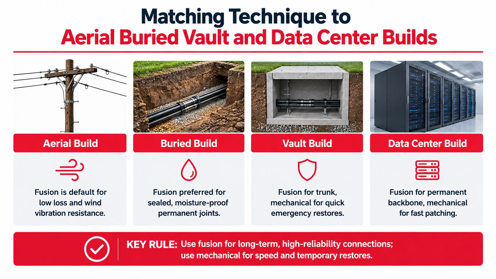
The environment changes the risk profile. An aerial closure sees movement and weather exposure. A buried closure prioritizes sealing and long-term stability. A vault may impose access and power constraints. A data center adds density, strict routing, and pressure to bring systems online quickly.
Aerial builds
Use single-fiber fusion as the default for a permanent aerial joint. Low loss and a fused glass structure suit spans exposed to movement, vibration, and repeated weather cycles. Mechanical splicing can be a sensible emergency bridge when the crew must restore service before full fusion equipment is available, but plan the permanent rework rather than leaving the temporary method untracked.
Selection rule: Aerial permanent repair means fusion. Use mechanical only when restoration constraints make it an interim measure.
Buried plant
Use fusion inside a properly sealed splice closure. High-count ribbonized backbone cables favor ribbon or mass fusion because parallel processing reduces tray congestion and simplifies the organization of many permanent joints. The closure still needs correct slack storage, water blocking, cable preparation, and fiber identification.
Selection rule: Buried permanent plant means fusion, and ribbon fusion when the cable and closure are designed for it.
Splice vaults
A vault repair often demands a practical compromise. Fusion is the preferred permanent trunk method, but mechanical splicing can help during emergency restoration when powering a fusion splicer from a truck or portable pack is impractical. Protect the temporary joint, document it clearly, and schedule the permanent correction if the project's acceptance plan requires fusion.
For operators managing service records, billing, and infrastructure changes alongside restoration work, Centipid Technologies Ltd. provides context on ISP billing software and operational administration. Field documentation should still remain tied to the splice record and test file.
Selection rule: Vault trunk work means fusion where conditions permit. Mechanical is the rapid-restoration option, not the automatic permanent choice.
Data-center builds
Use single-fiber fusion for permanent backbone transitions and mass fusion for dense ribbonized spine, leaf, and campus pathways. Pre-terminated MPO assemblies can be appropriate when speed and factory control outweigh the flexibility of on-site splicing, but they don't eliminate the need to inspect, test, route, and document the installed pathway.
Project teams that coordinate construction, testing, and infrastructure records can also use Southern Tier Resources as a reference point for telecom infrastructure work. Selection rule: Data-center backbone work means fusion, mass fusion for high-count ribbon, and pre-terminated assemblies when the design prioritizes rapid deployment.
Common Failure Modes and How Crews Recover
Most bad splices leave clues. The machine may show a visible core defect, the power meter may fluctuate, or the OTDR may show a larger step than the estimated splice loss suggested. Don't replace equipment first. Trace the preparation and environment in order.
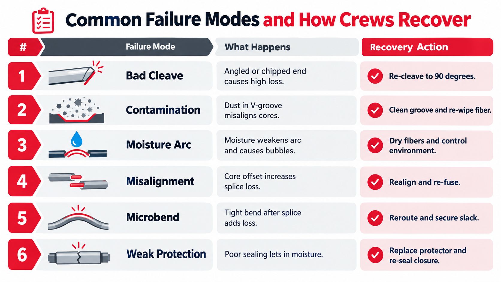
Match the symptom to the likely cause
- Bad cleave: An angled, chipped, or lipped end face can create high loss. Remove the damaged section, cleave again with a clean blade position, and inspect both ends before re-fusing.
- Contamination: Dust in a V-groove can shift the fiber or prevent stable alignment. Clean the groove, replace the wipe, and re-clean the bare glass.
- Moisture and arc instability: Moisture can produce bubbles or an inconsistent arc. Dry the fibers, improve the work enclosure, run the equipment's arc calibration, and re-splice.
- Core misalignment: A visible offset or repeated high estimated loss points toward alignment, fiber preparation, or an unsuitable profile. Re-prep both fibers and verify the correct fiber mode and splicer profile.
- Gel migration: A mechanical splice may show unstable performance if its gel or retaining hardware has moved. Replace the mechanical assembly rather than trying to restore a contaminated or compromised unit.
- Microbends and weak protection: A tight bend, poor slack route, or badly sealed protector can add loss or allow moisture into the joint. Re-route the fiber, replace the protector when necessary, and reseal the closure.
Don't chase the OTDR trace alone. Inspect the glass, check the splice hardware, then examine slack routing and closure sealing.
A junior crew lead can use this recovery order:
- Confirm the test setup, reference method, wavelength, and fiber identity.
- Inspect both fiber ends, the splice protector, and the tray route.
- Re-clean and re-cleave before changing machine settings.
- Check V-grooves, electrodes, arc calibration, holders, and the selected fiber profile.
- Re-splice, protect, and repeat insertion-loss and OTDR testing.
- Record the cause and correction, not just the final passing result.
That sequence prevents a common field mistake, adjusting arc current to compensate for a dirty cleave or a damaged fiber.
Where Fiber Splicing Techniques Are Heading Next
The familiar fusion-versus-mechanical decision is becoming too narrow for large network builds. Industry material points toward wider use of ribbonized trunks and mass fusion in hyperscale environments, where deployment teams need to control labor, rack space, and time to service. Prysmian's AI infrastructure analysis describes 16-fiber, 24-fiber, and emerging 32-fiber very-small-form-factor terminations, showing why single-fiber workflows can't be the only skill on a dense campus.
Specialty fibers create a different challenge. Lightera's OFC 2026 material emphasizes that multi-core fiber requires precise rotational clocking and that standard splicers may be inadequate. Hollow-core and multi-core work remains an emerging area, so crews should avoid treating existing single-mode acceptance assumptions as universal.
A practical equipment strategy follows from those pressures:
- Keep fusion capability current. Choose equipment that supports profile updates and the fiber types used by the project.
- Build ribbon competence. Mass fusion isn't an occasional specialty on high-count builds. It belongs in crew training and quality audits.
- Maintain test discipline. Calibrate the OTDR, inspection microscope, light source, and power meter, then preserve trace files with the splice records.
- Question inherited thresholds. New fiber constructions may need different preparation, alignment, arc, and inspection settings.
The crew that can select the method by environment, fiber construction, and restoration objective will outperform the crew that treats every joint as a single-fiber fusion task.
Southern Tier Resources supports fiber construction, expert splicing, testing, documentation, and data-center infrastructure fit-outs for carriers, ISPs, and facility operators. If your next build or restoration needs a field-ready splicing plan with reliable execution and records, visit Southern Tier Resources to discuss the project.