You're asked to add twenty desks, a few wireless access points, and cameras to a floor that already works. Nobody can say which wall outlets are live, where their cables end, or whether the run to the far office will carry the new switch speed. The switches aren't the problem. The undocumented cabling plant is.
A structured cabling network solves that by treating cables, pathways, and terminations as fixed building infrastructure. Electronics change every few years. A well designed plant stays in place, supports several generations of those electronics, and proves its condition through labels, test results, and drawings you can trust.
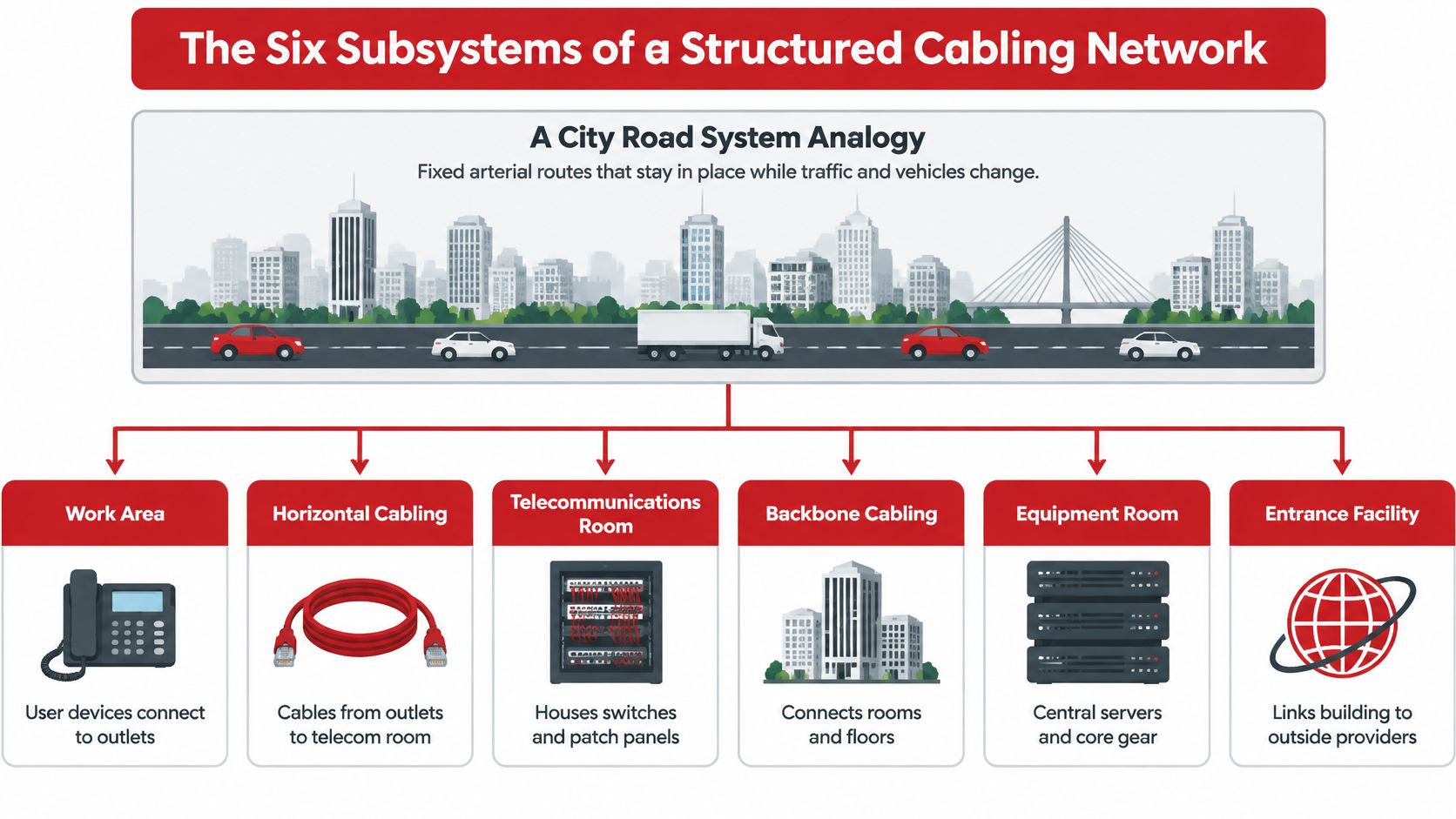
The Six Subsystems of a Structured Cabling Network
Think of a structured cabling network as a city's road system. Arterial routes, local streets, and driveways stay fixed while vehicles and traffic patterns change. You don't rebuild the city because a new model of car appears. You design the routes once, name them clearly, and let different traffic use them.
The work starts outside the building. The entrance facility is where carrier fiber or copper services enter, meet protection and demarcation hardware, and hand off to your internal plant. From there, services reach the equipment room, a central room for core switches, routers, servers, and the main cross-connect. This is the building's traffic interchange, not a storage closet with a rack squeezed in.
From the Core to the Desk
Backbone cabling links the equipment room to telecommunications rooms on each floor and, in a campus, to other buildings. Fiber suits these runs because distances are longer and aggregate traffic is higher. A telecommunications room on each floor terminates that backbone and the floor's horizontal cables on patch panels, with access switches mounted nearby.
Horizontal cabling is the fixed run from that floor's patch panel to a wall outlet. It's the local street. You install it once, certify it, and leave it alone. The work area is the final short stretch, the outlet, patch cord, phone, computer, camera, or access point at the desk or ceiling.
Say a team moves within a floor. You change patch cords in the telecommunications room and at the desk, update two labels, and you're done. The horizontal cable in the ceiling doesn't move. Say you replace access switches. You work in the telecommunications rooms while outlets and backbone fiber stay untouched.
| Subsystem | Typical Location | Typical Media | Role |
|---|---|---|---|
| Entrance facility | Building perimeter | Fiber and copper service cables | Where external carrier lines enter the building |
| Equipment room | Central building room | Core switches, routers, servers | Hosts core electronics and the main cross-connect |
| Backbone cabling | Between floors and rooms | Multimode and single-mode fiber, some copper | Links telecom rooms to the equipment room |
| Telecommunications room | Each floor | Patch panels and access switches | Terminates horizontal cables |
| Horizontal cabling | Floor to work area | Category 6A copper, some fiber | Fixed cable from telecom room to outlet |
| Work area | Desks and rooms | Outlets and patch cords | Where users connect devices |
That separation is also how physical cabling supports services that live elsewhere. Cloud applications still depend on a dependable local path to reach them, which is why planning a structured cabling network alongside resilient cloud infrastructure for startups makes sense for growing teams. The cloud provider can scale its platform quickly. Your building still needs ordered pathways, spare ports, and records.
Change should touch one subsystem at a time. If a desk move forces ceiling work, the plant isn't structured.
Confusion often starts with names. The equipment room and telecommunications room aren't interchangeable. One holds the core and serves the building. The others serve a floor or zone and keep horizontal runs short enough to certify.
Topology Options for Building Networks
Topology is the shape of connections, not the brand of cable. Choose the shape first, because it decides where every cable starts, where it ends, and what fails when someone cuts or disconnects it.
| Topology | How Devices Connect | Effect of One Cable Fault | Where It Fits |
|---|---|---|---|
| Bus | All devices share one trunk cable | A break takes down the whole segment | Legacy coaxial Ethernet only |
| Ring | Each device links to two neighbors | A break stops the ring unless it is protected | Older token-ring and some metro fiber |
| Point-to-point | Dedicated cable for each connection | Only that connection fails | Small installations, costly to scale |
| Star | Every device links to a central hub | Only that device's link fails | Modern Ethernet access |
| Hierarchical star | Outlets run to telecom rooms, rooms run to the core | One desk or one riser link fails | Enterprise and data center standard |
| Mesh | Many devices link to many others | Traffic reroutes around the fault | Redundant core and WAN links |
Most buildings use a hierarchical star. Each outlet has a home run to its floor telecommunications room. Each telecommunications room connects by backbone fiber to the equipment room, where the core sits.
Say a floor has 120 outlets served by three telecommunications rooms in a planning example. The nearest room terminates each outlet, so runs stay manageable and a damaged horizontal cable affects one desk, not forty neighbors. Place the rooms around the floor's geometry, not around leftover space, and measure the longest likely route, including rises, detours, and service loops.
A small office can collapse the hierarchy. One telecommunications room serves the whole suite, core and access switches share that room, and there's no separate backbone tier. That's still a star. It's a star with one center.
Don't add middle layers you don't need, and don't stretch one room across a floor it can't serve within length limits. Both mistakes look cheap on a drawing and expensive during certification.
How Standards Turned Wiring into a Star Layout
Early office wiring often grew application by application. A terminal system got its cable, phones got theirs, and shared coaxial Ethernet carried multiple stations on one segment. Adding a service meant pulling another route, and one segment fault could affect many users.
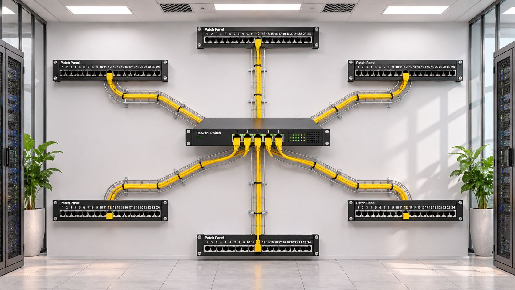
The photo below shows the modern result of moving away from that model, with switching and patching concentrated in an ordered field.
Ethernet standardization changed the physical layout step by step. According to IEEE Spectrum's account of the Ethernet milestone, Xerox, Digital Equipment Corporation, and Intel published a 10 Mbps specification in 1980, and IEEE adopted Ethernet as an official standard in June 1983. IEEE ratified 10BASE-T in September 1990, enabling 10 Mbps Ethernet over unshielded twisted pair.
Building wiring then caught up with the electronics. The Telecommunications Industry Association published TIA/EIA-568 in 1991, and the framework was adopted internationally through ISO/IEC 11801 in 1995. Generic horizontal cabling, telecommunications rooms, patching, and backbone links replaced wiring designed for one application.
Why the Star Won
Picture a hub and spokes without picturing a literal hub device. The telecommunications room sits at the center, and each outlet gets its own spoke. A failed spoke removes one work area. Technicians can disconnect, test, and label that link without disturbing neighboring outlets.
This short video walkthrough helps connect that patching concept to the rooms and panels you'll see on site.
The deeper change was separation of lifetimes. Standards allowed owners to install a cabling plant once and then replace electronics as speeds rose. Fixed pathways, consistent terminations, labels, and certification records made that possible.
Plan from the telecommunications rooms outward. First fix room locations, pathway routes, and backbone connections. Then assign outlets to the nearest room, check the longest routes, and reserve spare capacity. If you start by placing devices and dragging cables toward any available switch, you'll recreate point to point wiring inside expensive cable tray.
Permanent Link and Channel Limits That Decide Your Design
Two terms decide whether a copper design passes on paper. The permanent link is the fixed installed cable and its end connections. The channel is the whole path in service, including patch cords and equipment cords at both ends.
Under the ANSI/TIA model described in Panduit's guide to minimizing installed cost of high speed data center links, a permanent link contains up to 90 m (295 ft) of horizontal copper cabling plus end connections, while the channel also includes equipment and patch cords. That split produces the familiar design allowance of up to 10 m of cords within a 100 m channel.
Do the arithmetic before you route cable. A 95 m horizontal run in a worked check already fails the permanent link limit, even if both patch cords are very short. Shortening a desk cord can't rescue fixed cable that's too long. Move the telecommunications room, add a room, reroute the pathway, or serve that outlet from a closer room.
What Certification Actually Tests
A certifier doesn't merely check continuity. Field certification should verify wire map, length, insertion loss, NEXT, power-sum NEXT, far-end crosstalk, return loss, propagation delay, and delay skew. Each result points to a different physical problem.
- Wire map and length: Finds reversed, split, or miswired pairs and confirms the installed route matches the length model.
- Insertion loss: Shows how much signal the link absorbs. Excessive loss reduces receiver margin.
- NEXT and power-sum NEXT: Measures unwanted coupling between pairs near the transmitter, including the combined effect of multiple disturbers.
- Far-end crosstalk: Checks coupling that appears at the far end of the link.
- Return loss: Reveals reflections from impedance discontinuities, often caused by poor terminations or mismatched components.
- Propagation delay and delay skew: Confirms signals arrive within timing expectations and that pairs don't drift too far apart in arrival time.
Patch cords matter because they aren't electrically invisible. Cords, connectors, and cross-connects add insertion loss, return loss, and crosstalk. A permanent link can pass in isolation while the completed channel performs poorly with damaged, overly long, or poorly specified cords.
Practical rule: Certify the fixed plant, then control what gets patched into it. An uncontrolled cord drawer can undo a certified installation.
Use a certifier and test adapters rated for the category you're claiming. Save the native result files, not only a printed pass summary. Native files preserve margins, tester identification, limits, and the exact link identifier you'll need during a later dispute or upgrade audit.
| Segment or Application | Maximum Length | Media | Notes |
|---|---|---|---|
| Permanent link (horizontal) | 90 m (295 ft) | Copper | Fixed installed cable plus end connections |
| Channel (end to end) | 100 m | Copper | Permanent link plus up to 10 m of patch cords |
| 10GBASE-T over Cat 6A channel | 100 m | Copper | Full 10 Gb/s over balanced twisted pair |
| 10GBASE-SR over OM3 multimode | Confirm per IEEE 802.3 | Fiber | Short building backbone runs |
| 10GBASE-SR over OM4 multimode | Confirm per IEEE 802.3 | Fiber | Common choice for building backbones |
| 10GBASE-LR over single-mode | 10 km | Fiber | Campus and long backbone links |
Fiber limits work differently. Distance depends on the optical application, fiber type, connector count, splice loss, and the transceiver's loss budget. Confirm OM3 and OM4 reach against the IEEE 802.3 specification and the selected optics before you lock a backbone design. Don't copy a reach figure from a cable datasheet alone.
Read the copper rows as one chain. Fixed cable gets the large allowance because it's installed once and should last. Cords get the small allowance because they're flexible, handled often, and easy to replace. Spending the full channel budget in the ceiling leaves no room for normal patching at either end.
Choosing Cable Class and Media for Each Run
A class rating belongs to the complete installed link. It isn't a promise printed on a reel. Cable, jacks, patch panels, plugs, cords, termination quality, and routing all shape the result you certify.
| ISO/IEC Class | Category | Bandwidth | Typical Use |
|---|---|---|---|
| Class D | Cat 5e | 100 MHz | 1 Gb/s Ethernet |
| Class E | Cat 6 | 250 MHz | 1 Gb/s Ethernet; 10 Gb/s only on short runs |
| Class EA | Cat 6A | 500 MHz | 10 Gb/s Ethernet up to 100 m |
The bandwidth mapping in FS's ISO/IEC 11801 glossary lists Class D at 100 MHz, Class E at 250 MHz, and Class EA at 500 MHz, with Class EA corresponding to Cat 6A class performance for 10 Gb/s Ethernet over balanced twisted pair. Read those numbers as installed performance classes, not as component shopping labels.
Matching the Class to the Job
Use Cat 6A as the practical baseline for new horizontal copper when the plant must support 10 Gb/s within its life. The larger cable and tighter termination discipline cost more during installation, but replacing ceiling cable later costs far more in access, labor, and disruption. Cat 6 still suits limited 1 Gb/s work, but don't present it as a full distance 10 Gb/s plant. Its useful 10 Gb/s reach is shorter and needs careful alien crosstalk control.
Existing Cat 5e isn't automatically waste. If it's documented, within length, and certifies with margin, it can keep carrying suitable 1 Gb/s services. Judge it with tests, not age or jacket color.
Wireless access points expose weak horizontal decisions quickly. The radio may be new while its uplink and power delivery depend on an old, marginal run. If users blame coverage, check the wired path first and fix slow Wi-Fi with wired cabling where tests show the access point link is the constraint.
Alien crosstalk is the failure mode readers often miss. It's coupling between adjacent cables, not only between pairs inside one cable. Large, tight bundles of high frequency copper links can disturb each other even when individual cables look sound. Follow the component manufacturer's bundle, fill, and separation guidance, dress bundles without crushing them, and use hook and loop ties rather than overtightened plastic ties.
When Fiber Is the Better Run
Choose fiber for backbones, campus links, electrically noisy routes, and places where copper distance or bundle congestion creates a design constraint. Multimode OM4 commonly serves short building backbone runs with suitable optics. Single-mode suits longer backbone and campus routes and gives you broad transceiver choice across distance.
Fiber doesn't remove workmanship. Polarity, connector cleanliness, bend radius, slack storage, and splice records decide whether the optical budget survives installation. Inspect and clean endfaces before mating them. A dirty connector can consume margin that the design reserved for future connectors or repairs.
Before ordering, write a short specification with six items:
- Target class: State ISO/TIA class and the applications it must support.
- Length model: Set maximum permanent link and channel lengths for every area.
- Approved component family: Keep cable, jacks, panels, and cords within a tested system.
- Pathway rules: Define fill, bundling, separation from power, and bend radius controls.
- Identification: Fix label format, outlet numbering, panel naming, and drawing symbols.
- Acceptance tests: Name test limits, tester requirements, file format, and who reviews failures.
Match the class to the fastest electronics you plausibly plan during the plant's life. Buying only for today's switch is how a new installation becomes the next upgrade project.
Where Enterprise and Data Center Designs Diverge
Enterprise offices and data centers use the same physics. They diverge in density, change rate, and the cost of reaching a connector after the room is live. An office technician may patch a few desks each week. A data center team may build rows of inter-rack links under a fixed commissioning date.
The image below contrasts an enterprise telecommunications room with a larger server aisle, where pathways and access space become design features rather than leftovers.
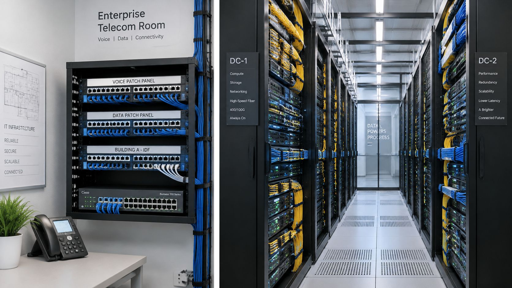
According to CommScope's 2026 data center eBook, AI clusters use more high-speed inter-rack cabling and fiber than traditional data-center networks, upcoming 800G and 1.6T deployments rely on 200 Gb/s lanes and higher-fiber-count architectures, and reporting describes rack power densities above 80 kW. Direct data-center interconnect capacity is expected to increase threefold between 2025 and 2028, a projection that puts pathway space under pressure well before the electronics arrive.
Density Has an Operating Cost
Conventional MPO/MTP systems remain workable, widely understood, and easy to staff. Very-small-form-factor connectors can provide nearly triple the density of conventional MPO/MTP systems. Pre-terminated trunks shorten field work and move much of the termination quality control to the factory. Modular cassettes make polarity and breakout changes easier when tenants or switch generations change.
Don't rank those options by ports per rack unit alone. An ultra-dense field can trap fingers, hide labels, slow cleaning, and make one faulty connector hard to isolate without disturbing neighbors. That raises the cost of moves, adds, and changes for years. A slightly larger patching field with clear slack routes may deliver lower lifecycle cost.
The densest panel you can buy isn't always the cheapest panel you can operate.
Pathways decide whether density stays serviceable. Reserve tray and vertical manager capacity, protect bend radius at every turn, keep slack in defined storage points, and plan connector cleaning access. Liquid cooling lines and overhead busways now compete for the same space, so route cabling pathways early with mechanical and electrical trades, not after their equipment is fixed.
Use different decision rules for different buildings:
- Hyperscale data center: Favor planned pathways, high-count pre-terminated fiber, repeatable polarity methods, and spare trunk capacity for row expansion.
- Enterprise office: Favor Cat 6A horizontal copper, accessible telecommunications rooms, modular outlets, and labels a general facilities technician can follow.
- Colocation facility: Favor modular cassettes and flexible cross-connect fields, because tenant density and interface types change during the lease.
The office design values simple changes across many small work areas. The hyperscale design values repeatable volume and fast row delivery. Colocation values adaptability between unknown future tenants. Copying one environment's connector strategy into another usually preserves the visible hardware while losing the reason it worked.
Designing for Upgrades Without Wasting Installed Plant
Future proof is not a cable category. It's a measurable condition. A plant can contain suitable media and still block an upgrade because nobody knows its polarity, loss, route, connector type, or remaining pathway space.
The direction of optics makes records more valuable. As described by Cables Plus USA's 2026 data center trends overview, IEEE 802.3dj work is expected to support 800G over eight fibers and 1.6T over 16 fibers using 200 Gb/s lanes. Your fiber type, connector choice, polarity scheme, and loss budget can therefore either enable a transceiver change or force new trunks and cassettes.
Score Upgrade Readiness
Score each item pass, partial, or fail with evidence attached. Don't award a pass because someone remembers an installation fondly.
- Spare pathway capacity: Trays, conduits, sleeves, and managers have room for planned cables without exceeding fill or bend radius rules.
- Optical-loss margin: Measured link loss leaves margin against the next application's budget after planned connectors are included.
- Test-document completeness: Native copper results, optical loss results, endface records, and as-built routes match current labels.
- Connector and cassette availability: Installed interfaces are obtainable and compatible with planned breakout or trunk arrangements.
- Port-density headroom: Panels and switches have usable spare ports, not ports stranded by polarity or blocked access.
- Transceiver compatibility: Fiber type and connector arrangement suit likely next generation optics and lane counts.
Six passes mean retain. Keep the plant, update electronics, and spend money only on patching and any optics the upgrade needs. Four or five passes with sound media but weak records or loss margin mean re-terminate or remediate. Clean and inspect connectors, replace damaged cords, correct labels, rebuild polarity records, retest, and replace only the terminations or cassettes that block the target.
Any failure on spare pathway capacity, or media that can't meet the target class, means replace that portion. New pathways may matter more than new cable. Pulling higher performance media into a full tray with crushed bends gives you an expensive link that still can't be serviced.
Replacing a functioning plant early creates material waste and stranded capital. Retaining an undocumented plant without testing creates a different waste, failed cutovers and emergency troubleshooting. The readiness score forces a third option, prove what's sound, repair what's local, and reserve replacement for limits you can't remediate.
Confirm the Design and Documentation Before You Install
A cable plant can outlast several generations of network equipment. Before ordering materials or scheduling installers, confirm that the design records not only what will be installed, but also how the links can be tested, maintained, and upgraded.
- Map subsystems: Mark the entrance, equipment room, backbone routes, telecommunications rooms, horizontal zones, and work areas on the floor drawings.
- Schedule every link: Record each link's class, medium, source, destination, and channel length. Use wired network tips from Forward Electrical to review installation details that may affect the plan.
- Write the test plan: Specify permanent link and channel parameters, tester requirements, how failures will be reviewed, and which result files must be delivered.
- Define records: Set the labeling scheme and document as-built routes, patching history, connector endfaces, and test baselines. Chris from SnapDial said, “They delivered the project on time and provided detailed as-built plans.”
- Hold a review point: Score upgrade readiness and resolve pathway conflicts before cable is pulled.
Keep the drawings, class schedule, and test plan together so installers and reviewers can trace each link from route to test result. For data center projects, clarify how infrastructure fit-out work connects power, connectivity, and structured cabling. Southern Tier Resources provides end-to-end services, from design to deployment and maintenance.
For a data center, carrier facility, or enterprise site, Southern Tier Resources offers engineering, construction, fiber splicing, testing, and documented handoff. Visit Southern Tier Resources to discuss your routes, readiness score, and installation schedule before materials are ordered.