The global data-center structured-cabling segment grew by almost 35% in 2024, according to BSRIA's structured-cabling market update. That investment isn't just about faster connections. Owners also need physical infrastructure they can reach, repair, and rearrange as racks demand more power and different cooling.
The difficult question is not just which cable to buy. It is whether a technician can replace a trunk, identify a port, or work around new cooling hardware without interrupting neighboring services.
What Structured Cabling Is and Why the Plant Outlasts the Gear
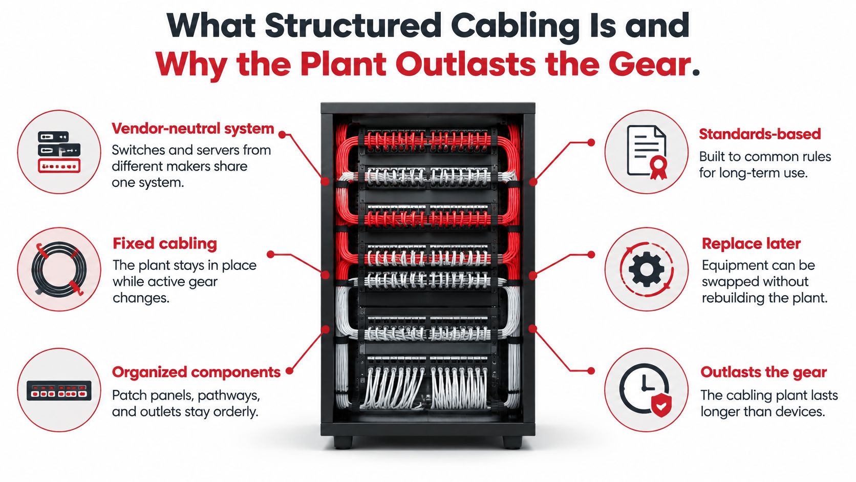
A structured cabling plant can outlast several generations of network equipment. It is a standards-based, vendor-neutral system of fixed cables, backbone links, patching, pathways, and labels, designed to support changes without replacing every installed connection.
When an enterprise replaces switches or rearranges an office, technicians can update equipment connections and patch assignments while leaving most of the plant in place. Without an organized system, each change can require another cable pull through an increasingly crowded ceiling.
The structured cabling market continued to grow in 2024, reflecting ongoing investment in the physical foundation beneath network equipment.
Build streets rather than temporary routes
A street grid is a useful analogy. Equipment is the traffic; the cable plant is the streets. Changing vehicles does not require rebuilding the roads, and changing switches should not require replacing the fixed cabling.
The analogy has limits. A road grid does not guarantee that every vehicle can travel every route. Likewise, a structured plant does not guarantee that every application will work over every cable. Designers must match the intended service to the complete connection.
For context on how cabling fits among essential IT infrastructure components, it helps to consider the systems it supports, including computing, storage, and networking.
Different sites need different decisions
An office floor needs accessible outlets and predictable moves. A data hall needs patching that remains manageable around dense racks. Carrier and ISP sites need clear service boundaries, while a municipal fiber entrance needs a clear transition between outside and inside infrastructure.
Start with four operational questions:
- Application: What connection must the complete installed path support?
- Physical change: Where might racks, desks, power distribution, or cooling equipment move?
- Acceptance: What evidence will show that the installation works?
- Ownership: Who will maintain the records after turnover?
Choosing the highest copper category everywhere does not answer these questions. A premium cable trapped behind cooling equipment can be harder to maintain than a properly selected cable on an accessible route. The plant's pathways and records matter as much as the cable specification, especially as racks become denser and hotter.
Practical rule: Specify what technicians must be able to change, test, and identify, not only what the cable jacket must say.
Channel Lengths and the Standards That Set Them
ANSI/TIA-568-B established the widely used 90-meter maximum horizontal permanent link and 100-meter maximum channel, with the additional distance allocated to patch cords and equipment connections, as described in the Fiber Optic Association's premises-cabling overview. That allowance isn't permission to hide more horizontal cable above the ceiling.
Measure the installed route, including changes in elevation and managed slack. A straight line on a floor plan isn't the cable length, and placing the telecommunications room in a convenient leftover space can make otherwise sensible workstation locations unreachable.
Specify the whole connection
The permanent link is the fixed installed portion. The channel includes the patch cords and equipment cords that complete the connection in service.
ISO/IEC 11801 distinguishes these configurations and addresses insertion loss and near-end crosstalk, commonly called NEXT. That distinction matters because a permanent-link pass doesn't automatically prove that the operational channel will pass.
A poor cord can add excessive loss. A damaged plug can create reflections, measured as return loss. Closely coupled signals can interfere with adjacent pairs, while patching choices can consume margin the fixed installation preserved.
Don't treat cable category as a substitute for application engineering. Name the required service, select a compatible channel construction, and control the connections between endpoints.
Where each structured-cabling medium belongs
| Medium or space | Governing standard | Length or reach rule | Typical use | Limit that bites first |
|---|---|---|---|---|
| Horizontal copper, usually Cat 6A | ANSI/TIA-568 | Separate permanent-link and complete-channel limits | Work areas and some cabinet links | Patch-cord loss can fail an otherwise compliant fixed link |
| Multimode fiber | ANSI/TIA-568 and TIA-942 | Short data-hall trunks sized to the Ethernet application | Cabinet-to-cabinet and row trunks | Dirty connectors and wrong polarity |
| Single-mode fiber | ANSI/TIA-568 plus outside-plant practice | Campus, carrier, and long backbone spans sized to the optical application | Entrance rooms and building-to-building links | Splices and bends that an OTDR helps locate |
| Data center spaces | ANSI/TIA-942 | Application reach, not a blanket copper-channel limit | Racks, pathways, main distribution area and horizontal distribution area | Later power and cooling hardware consuming pathway space |
Read the table as a set of constraints
Horizontal copper is useful where devices need familiar electrical interfaces, including endpoints powered through their network connection. Category 6A is a common design choice for demanding horizontal applications, but the designer still has to verify the intended Ethernet service against the completed channel.
Multimode fiber can suit short data-hall trunks. Its reach must match the selected optics and application, not a generic assumption that fiber reaches anywhere in the room. Single-mode is often the more useful starting point for campus routes, carrier facilities, and longer backbones.
The data-center row describes a space-planning standard, not a separate transmission medium. Main and horizontal distribution areas organize connectivity; they don't remove the reach restrictions imposed by the selected application.
Write the applicable standards family and the exact adopted revision into the specification. Avoid undated references that leave the designer, installer, and acceptance technician working from different editions.
The same separation of responsibilities applies to security. Splash Access's discussion of Meraki MX threat protection concerns network security functionality; specifying that functionality doesn't establish whether its physical connections meet their channel requirements.
Before procurement, approve the application, medium, connection arrangement, connector budget, and acceptance limit together. Otherwise, separately compliant products can still form an unsuitable connection.
Six Subsystems From Entrance to Desk
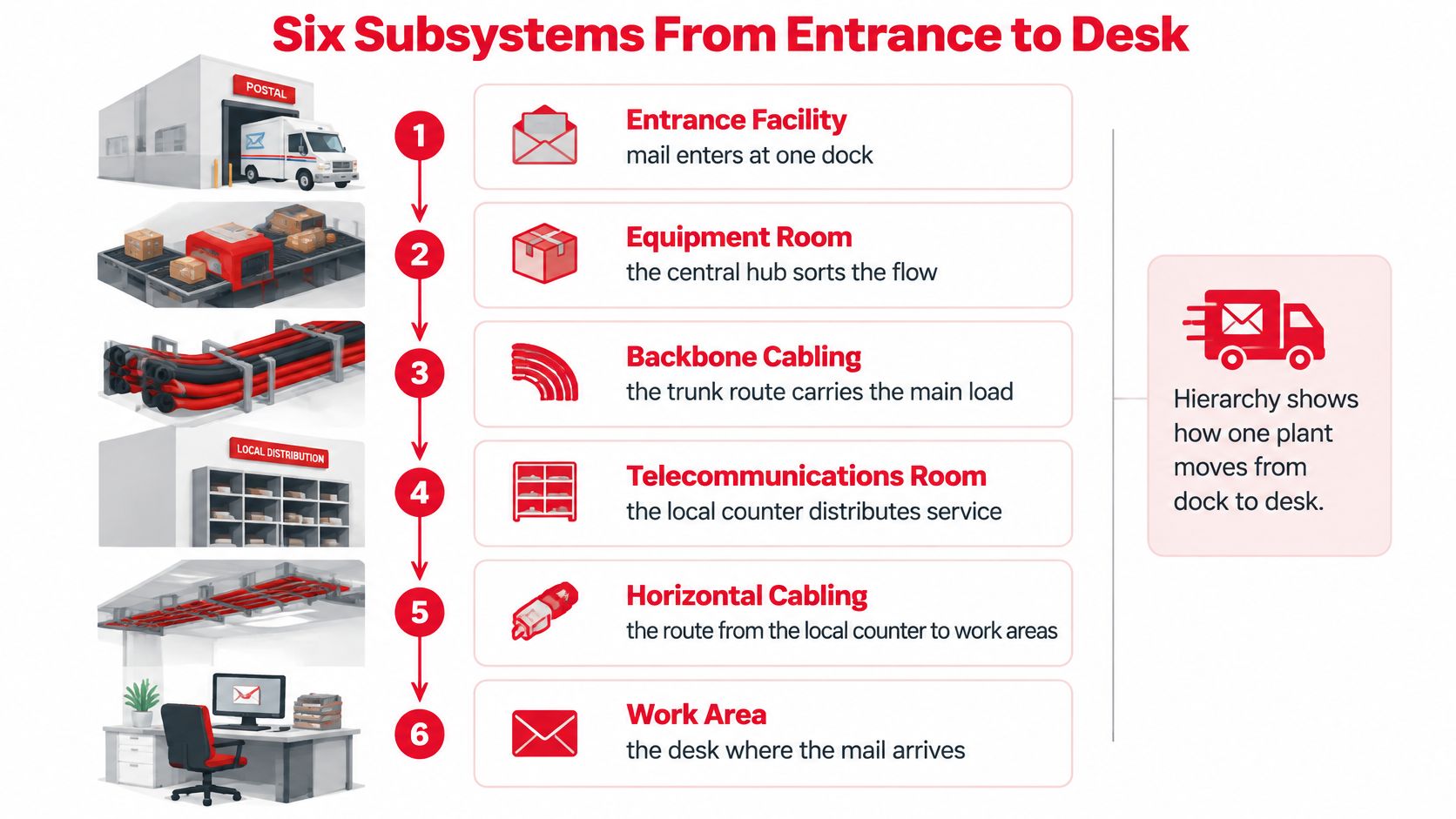
A postal network makes the cabling hierarchy easier to follow. Mail enters at a receiving dock, moves through a sorting hub and trunk route, and reaches a local counter before delivery. A building's communications plant follows a similar progression, with a defined job at each stage.
The hierarchy diagram shows how those jobs fit together.
From the receiving dock to local distribution
At the entrance facility, carrier or outside-plant cable reaches the building. Designers establish the service boundary, suitable cable transitions, splice arrangements, and protection. Bond metallic cable elements and associated hardware where required; dielectric fiber itself isn't something you ground.
The equipment room acts as the central sorting hub. Core switches, main cross-connects, and fiber distribution frames belong in a space where technicians can identify incoming services and outgoing building connections without tracing cables through unrelated equipment.
Backbone cabling carries those connections toward other buildings or telecommunications rooms. Single-mode fiber is a practical choice between buildings, while an internal backbone may use single-mode, multimode, or a deliberately selected combination.
The telecommunications room serves local areas. Treat it as working infrastructure, not overflow storage for furniture, packaging, or cleaning supplies. Technicians need room to open cabinets, read labels, and reach termination fields.
From local distribution to the endpoint
Horizontal cabling runs from that local room toward work-area outlets. Position the room and select routes before finalizing desk layouts, rather than discovering after construction that distant outlets require an unsuitable connection.
The work area contains the outlet, faceplate, and equipment cord that serves the user device. Keeping this boundary simple makes furniture changes easier and reduces the temptation to extend fixed wiring through improvised adapters.
A practical hierarchy also needs an intentional patching arrangement:
- Cross-connect: A separate patching field lets technicians rearrange services without handling equipment ports directly. It adds flexibility, but also adds connections that must fit the channel budget.
- Interconnect: Equipment connects directly to the distribution patching field. This reduces intermediate hardware where space or optical margin is tight.
- Managed termination: Racks, cabinets, patch panels, and cable managers support moves through deliberate patch changes rather than replacement cable pulls.
Give every subsystem a named space and an approved pathway before ordering cable.
The work-area boundary is also where infrastructure acceptance meets application acceptance. A correctly terminated outlet doesn't prove that a phone registers, receives power correctly, or handles calls as intended.
SnapDial's guidance to test your new business phone system is useful when planning that separate operational check. Keep application testing in the turnover plan, but don't use a successful call as evidence that the underlying cable meets its specified performance.
Pathways Built for Denser and Hotter Racks
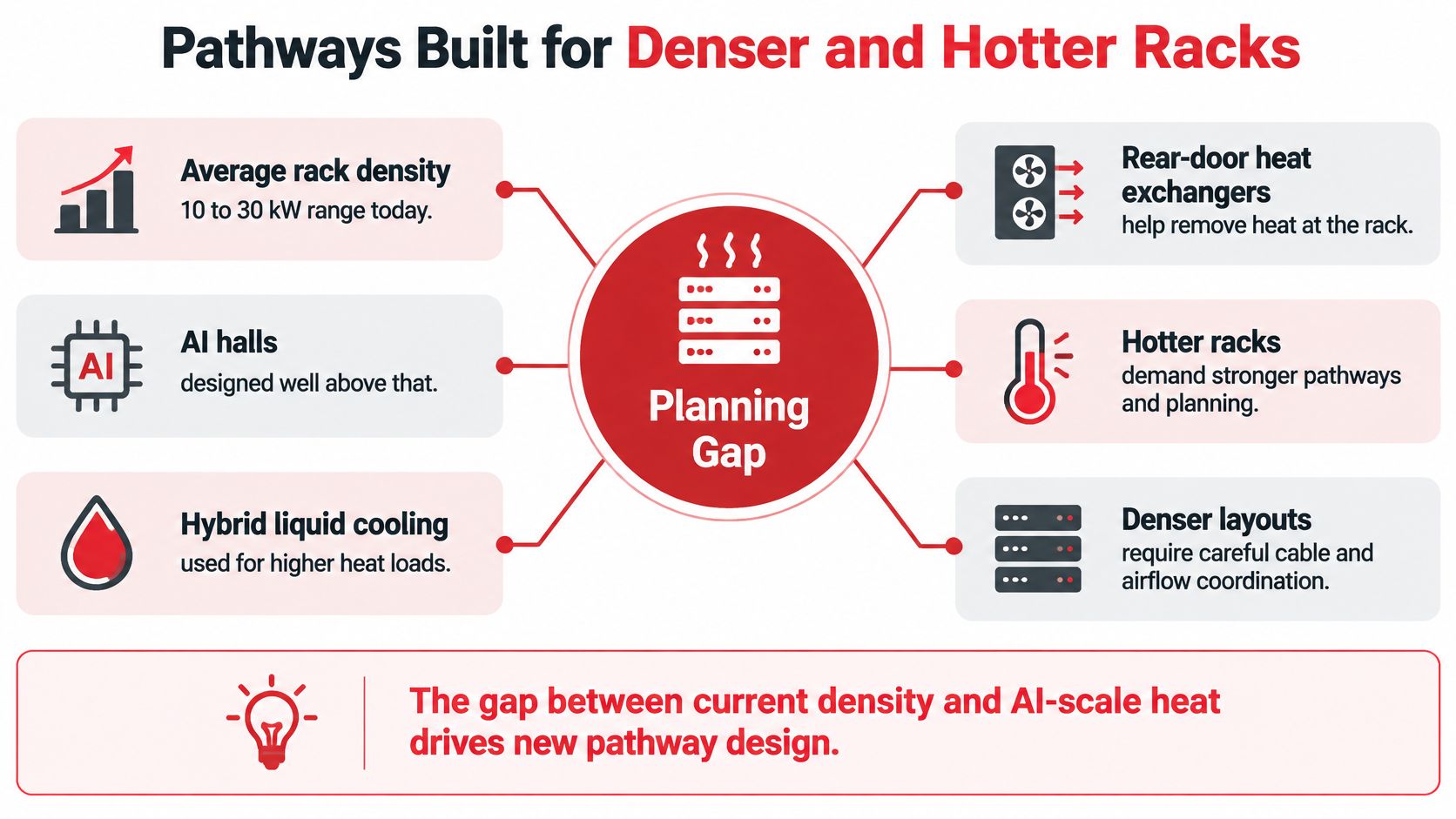
Average rack density has risen into the 10–30 kW range, while AI-oriented facilities are preparing for substantially higher densities and hybrid liquid cooling, according to Uptime Institute's annual global data-center survey findings. Cable category doesn't answer the physical questions that shift creates.
A rack might have adequate network bandwidth but no usable path for its next trunk. A neatly installed patch field might become inaccessible after a rear-door heat exchanger arrives. Larger power connections can occupy the space a designer assumed would remain available for communications.
The planning gap is physical as much as electrical.
Reserve usable space rather than empty-looking space
Size trays and baskets against an agreed expansion scenario. Reserve enough accessible capacity for the next intended trunk, including the space needed to install it without pulling across live fibers.
Check the full route, not only the straight tray sections. Waterfalls, intersections, cabinet entries, and transitions between overhead and vertical management often become significant constraints. A large basket doesn't help if every cable must squeeze through an undersized cabinet opening.
Coordinate communications routes with power distribution and cooling hardware on the same drawings. A ladder that looks empty isn't spare capacity if the facilities team has already allocated that aisle to busway or pipework.
- Bend protection: Provide radius-controlled transitions where cables leave trays or enter cabinets.
- Service access: Keep patching reachable with doors, cooling equipment, and containment panels in their operating positions.
- Managed slack: Place service loops where technicians can retrieve them without disturbing neighboring circuits.
- Separation: Establish power and communications separation from the applicable installation rules and equipment requirements, not a visual guess.
Choose flexibility where change is likely
Consider a stable office area and a frequently rebuilt accelerator row. The office may benefit from a consistent copper installation matched to endpoint requirements. The accelerator row may benefit more from modular fiber trunks, diverse routes, and identified spare ports than from an indiscriminate copper upgrade.
Route diversity needs physical verification. Separate patch panels don't provide diverse paths if their trunks share the same vulnerable tray or penetration.
For an existing facility, inspect the installed tray, penetrations, firestop systems, and abandoned cable before promising more density. Confirm whether obsolete cabling can be removed safely and whether proposed changes will disturb existing firestopping.
A useful design review asks the team to show the next change on the drawing. Where will the new trunk enter? Which cabinet opening will it use? Can someone replace a cooling component without moving live network connections?
Use the following video as a supplementary visual reference while considering rack and pathway arrangements.
Before approving the layout, resolve application reach, accessible pathway spare, connector budget, and the cooling or power changes already on the roadmap. Record the reserved spaces explicitly so another trade doesn't consume them during construction.
The more expensive cable isn't automatically the more adaptable investment. Sometimes the valuable purchase is an accessible alternate route and the discipline to keep it available.
How to Certify Copper and Fiber Links
Prepare the instruments. Confirm calibration status on the copper certification tester and optical loss test set. Inspect test adapters, establish the optical reference using the specified method, and record that method with the results.
Test every copper permanent link against the selected acceptance limit. Include wire map, length, insertion loss, NEXT, return loss, and the other parameters required by the specified performance class. A continuity tester isn't a substitute for a certification instrument.
Verify the service configuration. Test the completed copper channel with the intended cord arrangement before turn-up. Record the cord and patching configuration, especially where the fixed installation has limited remaining margin.
For fiber, perform Tier 1 certification, including end-to-end insertion loss, length, and polarity; Tier 2 adds OTDR traces rather than replacing the loss test, as explained in Anvil Field's TIA-based field guidance. Apply the specified checks to duplex connections and MPO or MTP trunks, using test interfaces appropriate to their construction.
Add fault-location evidence where needed. Obtain OTDR traces for long single-mode spans, dense trunks, and links needing event-level diagnosis. Use launch and receive fibers suitable for the test arrangement so end connections can be assessed meaningfully.
Tie every result to the physical port identifier and compare it with the written acceptance budget at the specified wavelength. Resolve failures, document retests, and retain native instrument files rather than handing over only a summary marked pass.
Know what the measurement actually proves
An optical loss test establishes whether the entire connection stays within its allowed loss budget. An optical time-domain reflectometer, or OTDR, provides distance-based evidence that helps locate excess loss or reflection.
These measurements answer different questions. A trace may help distinguish a problematic connector, splice, bend, or damaged cable section, but technicians may still need inspection and targeted testing to confirm the cause.
Dense multifiber connections deserve particular care. A defective MPO interface can consume much of a short link's available margin, even when the rest of the trunk is sound.
Acceptance tests and the record each one produces
| Test | What it proves | When to require it | Record to keep |
|---|---|---|---|
| Copper permanent link | Wire map, length, loss, NEXT, and return loss of the fixed installation | Every installed copper link | Native tester file tied to the port ID |
| Copper channel | Performance with the cords and connectors used in service | Before turn-up and after cord changes on marginal links | Channel configuration and result |
| Fiber basic loss certification | End-to-end insertion loss, length, and polarity | Every duplex and MPO or MTP link | Loss result against the wavelength-specific budget |
| Fiber OTDR characterization | Where excess loss or reflection occurs | Long single-mode spans, dense trunks, and links needing fault localization | Native trace file for later comparison |
Reject ambiguous passes
Require the technician to select the correct test limit rather than a convenient default. A result has little value if the instrument tested a different cable class, reference arrangement, or link configuration from the one specified.
Also examine marginal results rather than treating every pass as equally reassuring. Check whether an unusual result follows the installed cable, a test adapter, or a patch cord before accepting the link.
Keep failed results and the explanation of corrective work alongside the final pass. That history can help a maintenance technician recognize a recurring termination problem instead of treating it as a new fault.
The owner needs usable evidence, not screenshots of green check marks. Acceptance files should remain searchable by the same identifiers technicians see on the physical installation.
Handover Records That Prevent the Next Outage
Network complexity and change-management errors recur as contributors to outages. That is why physical-layer records belong in day-to-day operations, not just in a project archive.
A clean installation can still become an operational hazard when the port map is wrong. A technician might unplug the wrong service, choose an unavailable fiber pair, or assume a temporary connection has been removed.
Make the turnover package navigable
Give each cable end and panel position a serialized identifier, then link those identifiers to route and termination records. Include rack elevations, fiber assignments and polarity, collected test files, and photographs that show crowded or concealed terminations.
State the acceptance thresholds used. For every exception, record the waived requirement, reason, approving owner, and any operating restriction that remains.
The package should work like a map: a reader starts with a physical outlet or fiber port and follows its identifier to the destination, route, test result, and current service assignment. Ask the installer to demonstrate that lookup.
Acceptance check: Give someone who didn't install the cable a port identifier. They should be able to find its destination and evidence without asking the installer.
Treat unidentified legacy infrastructure as a separate inventory problem. Survey and sample-test unknown links, compare labels with switch assignments, and certify any link selected for new service before relying on it.
Record suspected abandoned cable as unconfirmed until its status is established. A cable's presence and a fitting plug do not show that it is safe to connect new equipment.
Keep records aligned with work
A move, add, or change is complete only when its records match the new installation. During the same shift, update the port record, save new evidence alongside the baseline, and remove temporary patching or document why it remains.
Keep three operational records in agreement:
- Infrastructure inventory: DCIM, or a controlled spreadsheet serving that purpose, records physical locations and connections.
- Network source of truth: Service and equipment assignments match the installed patching.
- Maintenance log: Work orders identify affected ports, changes made, test evidence, and unresolved exceptions.
Assign an owner to reconcile the records. If teams maintain separate systems, specify which record controls each field and how they resolve conflicting entries.
Maintain the baseline after turnover
Before mating fiber connectors, inspect their end faces with a fiber inspection scope and clean contaminated surfaces with connector-appropriate tools. Inspect again afterward; cleaning alone does not confirm that the end face is clean.
After a repair, repeat the affected loss acceptance test. Retain updated OTDR evidence when event-level records are part of the maintenance plan, and log the work against the port identifier so recurring problems remain visible.
Set a recurring sample-retest schedule for heavily handled trunks, guided by service criticality and change activity. Compare results with the handover baseline and investigate deterioration before it becomes an unexplained interruption.
Installed cable is a construction deliverable. The records that let the next technician trace a connection and judge a repair are part of operable infrastructure.
Three Plants and What Changes in Each
The same engineering principles produce different layouts when the owner's constraints change. An enterprise refresh, a changing data hall, and a broadband entrance don't need identical bills of materials.
The illustration provides a visual reminder that structured cabling serves different working environments.
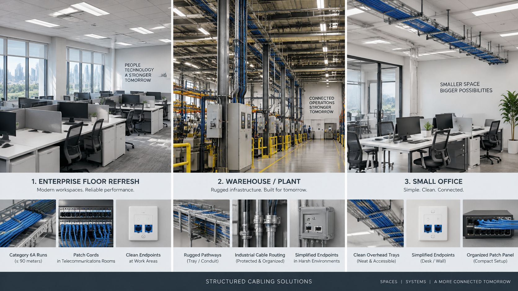
An enterprise floor refresh
Say an enterprise renovates a floor while neighboring departments remain occupied. The designer places telecommunications rooms around actual cable routes, selects Category 6A for the planned work-area applications, and uses a single-mode backbone suited to the intended riser services.
The immediate constraint is disruption. Installers need agreed access windows, identifiable work zones, and a cutover schedule that distinguishes new connections from those still carrying business traffic.
Desks will move after occupation. Provide patching that allows those moves without reopening ceilings, and keep room layouts accessible after furniture and storage arrive.
The installation can look finished while unlabeled copper creates a later failure. A technician relocating a department may disconnect an occupied outlet because the panel schedule doesn't match the room labels.
The record that exposes the problem is an outlet-to-panel schedule reconciled through physical verification. The owner should approve that mapping before accepting the floor.
A cloud or AI data-hall fit-out
A cloud tenant expects rack assignments to change as compute clusters are rebuilt. The design uses pre-terminated multimode or single-mode trunks selected for the optical application, with an explicit MPO polarity plan and accessible modular patching.
Here the constraint is access under changing conditions. Coordinate reserved cable routes with the cooling design, larger power distribution, containment, and the clearances needed to remove equipment.
A tray can look complete at opening and become the obstacle during the next row conversion. If the available route is already occupied, technicians may be forced to handle live trunks while trying to add another.
The document that exposes this risk is a coordinated pathway drawing showing occupied and reserved routes, cabinet-entry details, and planned facility additions. Keep trunk assignments and baseline traces attached to the affected route records.
A carrier or municipal broadband entrance
At a broadband entrance, outside-plant single-mode fiber transitions through a defined splice and termination arrangement into the inside plant. Establish responsibility for the incoming cable, splice enclosure, grounding and bonding of relevant metallic elements, and customer-facing handoff.
The outside span follows its own application and outside-plant engineering requirements. Don't apply a commercial-building copper-channel rule to that span or assume that an indoor patch-panel label fully describes it.
A closed splice case can look complete while an undocumented fiber assignment hides a later restoration problem. During an outage, crews may know the enclosure location but not which splice serves the failed port.
The record that catches the omission is an enclosure-level splice schedule linked to fiber identifiers, destination ports, and trace files. Test the record by tracing a selected service through the paperwork before anyone opens the enclosure.
Award the Plant You Can Still Change
Withhold award until the scope describes the operating system the owner will receive, not merely the material the contractor will install. A quotation for cable and connectors alone leaves too much room for disagreement at acceptance.
Put operating requirements into the contract
- Application and channel: Define the required service, selected medium, channel class, connection arrangement, and applicable acceptance limits.
- Pathway capacity: State the expansion scenario, protected routes, separation requirements, and access needed around planned power and cooling equipment.
- Test evidence: Identify the required copper certification, fiber loss testing, and OTDR characterization, including native files and the process for resolving failures.
- Handover and updates: Require labels, routes, results, photographs, exceptions, and a controlled update process for subsequent changes.
Evaluate bidders against that complete scope. Ask who owns coordination between design, installation, splicing, testing, and documentation, especially when several subcontractors share the work.
An integrated infrastructure contractor is one option; a coordinated group of specialists is another. Either arrangement needs clear accountability for interfaces and a named owner who checks that the delivered records match the installed plant.
Award the work on demonstrated maintainability, not the highest category offered.
A useful acceptance exercise is to select an unfamiliar port and ask the operations team to identify its route, destination, service assignment, and test evidence. Missing information should become a punch-list item, not an informal promise to send another file.
The operating test is straightforward: well after the construction crew leaves, a technician should be able to locate a failed port from the records without unplugging live neighbors. That's the difference between purchasing cable and purchasing infrastructure you can still change.
Southern Tier Resources offers engineering, installation, fiber splicing, testing, documentation, and maintenance for carrier, ISP, data-center, and enterprise infrastructure. To discuss structured cabling solutions that coordinate connectivity with pathways, power, cooling, and verified handover records, visit Southern Tier Resources.