In 2024, CommScope's Connectivity and Cable Solutions segment generated approximately $2.8 billion in net sales, roughly 51% of the company's $5.47 billion in total revenue (CommScope 2024 annual report). That is an enormous volume of glass and copper moving into carrier access networks, broadband distribution and data halls. It is also the least interesting number on a fiber project. The cable is the cheapest, most substitutable line on the budget. What decides whether a rural FTTx program or a metro trunk gets paid for, warranted and kept in service is the acceptance package behind the reel: baselines, bidirectional OTDR traces, splice records and as-builts that prove the installed plant performs the way the datasheet promised.
CommScope Fiber Cable Lines at a Glance
CommScope's fiber business traces back to a communications-infrastructure company founded in 1976, and the Connectivity and Cable Solutions segment now sells fiber and copper connectivity and cable into telecommunications, cable television, residential broadband, data centers and enterprise networks. That breadth explains why one catalog spans a 300 m link inside a data hall and a 30 km rural distribution span. The same supplier supports both, but not with the same construction, and not with the same acceptance evidence.
| Cable family | Typical construction | Environment | Key figures | Best for |
|---|---|---|---|---|
| OS2 single-mode loose-tube | Gel-filled or dry water-blocking tubes, individually buffered fibers | Aerial, duct, buried conduit | No armor; spliced fiber by fiber | Carrier outside plant, FTTx distribution, long spans |
| OS2 single-mode armored unitube | Corrugated-steel armor under HDPE jacket | Direct burial, harsh outdoor routes | 0.34 dB/km at 1310 nm, 0.22 dB/km at 1550 nm; 200 mm loaded / 160 mm unloaded minimum bend radius | Rural broadband, rodent-prone and rocky routes |
| Single-mode ribbon | Flat ribbons bonded into a sheath | Duct and metro trunk routes | Highest fiber density; mass fusion splices 12 fibers at once | Metro backbone, high-count trunk builds |
| OM3 multimode OFNP | 50 µm laser-optimized, indoor/outdoor jacket | Data center, campus indoor/outdoor | 300 m at 10 Gb/s over 850 nm; 3.20 dB/km maximum | Intra-hall links, short campus runs |
| OM4 multimode | 50 µm laser-optimized, plenum or riser | Data center, structured cabling | Longer reach than OM3 at the same speed; speed-upgrade headroom | Longer multimode reach and speed upgrades |
Read the table with three questions in order and the shortlist collapses fast.
Is the route indoor or outdoor? Indoor plenum and riser work needs the right jacket rating for the space it passes through. Outdoor plant needs UV-resistant jackets, water blocking and, on buried routes, mechanical protection.
Single-mode or multimode? Anything that leaves the building or crosses more than a few hundred meters is single-mode work. Data hall links stay multimode until speed or distance pushes them off OM3.
Which construction survives the route? Aerial lashed cable, duct pulls and direct burial stress the assembly differently. Armor answers rocks and rodents. Ribbon answers fiber count in a crowded duct.
The families themselves are narrowed down by how they are built. OS2 loose-tube is the default outside-plant choice because the tube isolates the glass from pulling and thermal movement. Armored unitube trades flexibility for crush resistance. Ribbon trades splicing convenience for density. OM3 and OM4 trade reach for cheaper optics. Every one of those trade-offs lands in the sections that follow, and the article closes with a specification and acceptance plan you can hand to a bidder.
Selection rule: choose the construction the route will punish you least for. Everything else is a datasheet conversation.
Single-Mode and Multimode Cable Fundamentals
Multimode and single-mode answer the same question with different physics. Picture a one-lane highway. Light in a single-mode core of roughly 9 µm has one path to follow, so the pulses arrive at the far end together and stay readable over tens of kilometers. Multimode is a wide road. A 50 µm laser-optimized core carries dozens of paths at once, and because those paths differ in length, the pulses smear by the time they reach the receiver. That smearing, called modal bandwidth, is what caps multimode distance long before attenuation becomes the problem.
The infographic below is the mental model worth carrying into every link budget.
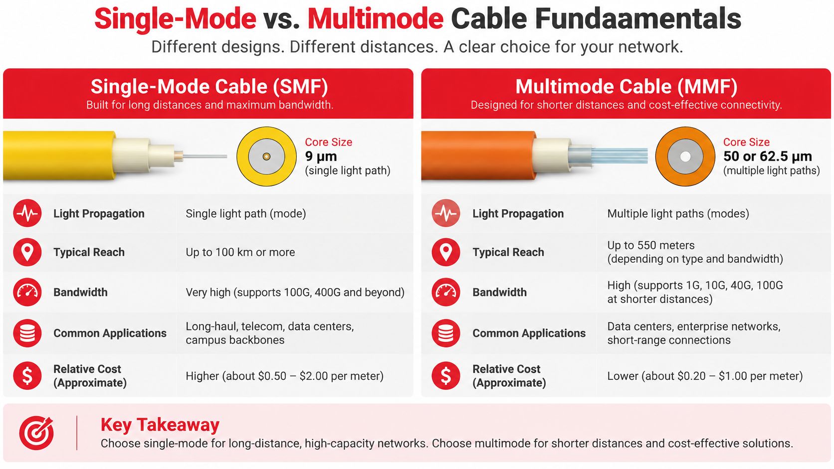
Designations follow that split. OS2 is standard single-mode, used at 1310 nm and 1550 nm and specified for the lowest loss per kilometer. OM3, OM4 and OM5 are graded multimode, used at 850 nm and 1300 nm, each grade buying more bandwidth and therefore more reach at a given speed. When a link budget is written, the wavelength and the fiber grade are not interchangeable details. They set the loss figure you multiply by distance.
The numbers on a real part make the point better than theory. CommScope's 6-fiber indoor/outdoor OM3 OFNP cable is rated for a 300 m reach at 10 Gb/s over 850 nm, with maximum attenuation of 3.20 dB/km at 850 nm and 1.00 dB/km at 1,300 nm (CommScope OM3 indoor/outdoor cable specifications). Run the arithmetic and the fiber contributes only about 0.96 dB across that 300 m at 850 nm, connectors and splices excluded. The cable is not eating the channel budget. Modal bandwidth, transceiver launch conditions, connector quality and installed polarity are the constraints that decide pass or fail.
Handling matters just as much. The same cable carries a minimum bend radius of 149.9 mm loaded and 71 mm unloaded. That loaded figure is tight enough that tight hook-and-loop dressing in a ladder rack, or a bundle compressed behind a cabinet door, can degrade a link that looked perfect on a visual inspection. Test insertion loss at the operating wavelength and verify polarity rather than trusting appearance.
Practical rule: inside the hall, multimode usually wins on optics cost. Past the OM3 rating, or once a speed upgrade is on the roadmap, price OS2 and stop guessing.
The most expensive mistake in this area is assuming OM3's 10 Gb/s rating scales to 25G, 40G or 100G because the connectors still fit. They do not. For longer multimode runs, price OM4 against single-mode; for anything spanning buildings, single-mode with the right optics is usually the cheaper total cost once you count the labor of replacing it later.
Loose-Tube Ribbon and Armored Constructions Compared
Catalog attenuation on the reel is not a passed span. I treat the acceptance package (baselines, bidirectional OTDR traces, splice records and traceability) as the actual deliverable of a CommScope cable buy, because installation complete is not network acceptance complete.
Three constructions carry nearly all outside-plant work, and each one solves a different failure mode. The construction also decides what the acceptance file has to show.
Loose-tube puts buffered fibers inside gel-filled or dry water-blocking tubes, so the tube takes the mechanical strain of pulling and thermal cycling while the glass floats inside it. It is the default for aerial, duct and buried conduit plant because it is forgiving to install, splices fiber by fiber with standard trays, and handles long pulls across varied terrain. Those individual fusion splices are the records you keep. A tray without a fiber map fails traceability even when every splice loss number looks fine.
Ribbon bonds fibers into flat ribbons that stack inside the sheath, which puts the highest fiber count into the smallest duct footprint. The payoff is mass fusion splicing, where the machine joins all 12 fibers of a ribbon in one cycle. The cost is breakout time: peeling ribbons apart for an individual splice is slow, and dressing a tray with stacked ribbons takes more care than loose tube. One bad cycle writes all 12 fibers into the splice log at once.
Armored construction wraps corrugated steel under an HDPE jacket. It answers crush loads, rocks and rodents on direct-buried routes, and it must be grounded and bonded at entries because the armor is conductive.
The armored unitube numbers show why the handling rules exist. CommScope's OS2 outdoor unitube with corrugated-steel armoring and an HDPE jacket is specified at a maximum of 0.34 dB/km at 1,310 nm and 0.22 dB/km at 1,550 nm, with minimum bend radii of 200 mm under load and 160 mm unloaded (CommScope armored outdoor unitube specifications). On a 10 km span, fiber attenuation alone contributes up to 3.4 dB at 1,310 nm or 2.2 dB at 1,550 nm before connectors, splices and engineering margin.
That 200 mm loaded radius is a routing constraint, not a suggestion. It applies during placement, at closure entry and in slack storage. Exceed it and you create macrobending loss that bites hardest at the longer wavelength, even when the cable's nominal attenuation looks compliant on paper. Armor and HDPE give you mechanical and environmental protection. They do not give you controlled pulling tension, and they do not replace post-installation OTDR verification in both directions against the baseline.
| Attribute | Loose-tube | Ribbon | Armored |
|---|---|---|---|
| Typical setting | Outdoor plant in aerial, duct, conduit | High-count trunk and metro duct routes | Direct burial, rocky or rodent-prone routes |
| Fiber density | Moderate, fibers grouped in tubes | Highest, more fibers per sheath diameter | Moderate, armor adds diameter and weight |
| Water protection | Gel-filled or dry water-blocking tubes | Water-blocking tapes and gels | Armor plus HDPE outer jacket |
| Mechanical protection | Standard jacket with tube buffering | Standard to armored options | Corrugated steel, crush and rodent resistant |
| Splicing approach | Individual fusion splicing | Mass fusion, 12 fibers per cycle | Individual fusion, longer prep time |
| Watch-outs | Pulling tension and bend radius | Ribbon breakout and tray dressing | Grounding, bonding, larger bend radius |
Where fiber hands off to copper and racks, the pathway and enclosure work gets just as particular. Finchum Fixes IT's Indiana structured cabling contractor guide is a practical reference for the contractor-side questions to settle before that scope goes out to bid.
Matching Cable to Project Conditions
Selection goes wrong in a predictable order, so run this list top to bottom and answer each line before moving down.
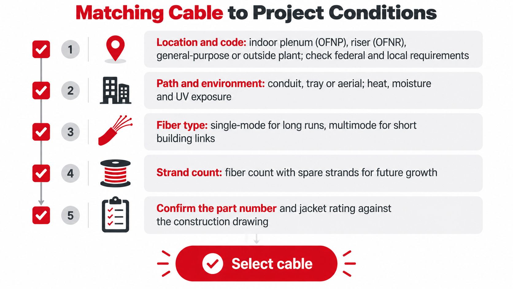
- Location and code. Indoor plenum space takes an OFNP rating, riser shafts take OFNR, and outside plant takes an outdoor-rated sheath. Federal or state broadband programs can layer their own testing requirements on top. The classic mistake is ordering a general-purpose jacket for a plenum return-air ceiling because the price looked better.
- Reach and speed. Match the fiber grade to the speed you plan to run at end of life, not the speed in this year's bill of materials. Assume nothing carries forward automatically during a transceiver refresh.
- Fiber count. Size for today's circuits plus growth, because labor, not glass, dominates the cost of adding strands later. The mistake that hurts most is buying exactly the count the current design needs and then paying for a second pull.
- Installation method. Aerial lashed, duct pulled, direct buried or indoor tray. Each one changes the sheath, the armor decision, the pulling tension and the splice prep.
- Pathway congestion. Take the loaded bend radius into crowded trays, handholes and closures and see whether the cable still fits. Cables that pass a straight-pull calculation often fail at the closure.
- Termination strategy. Factory-terminated assemblies buy speed and consistency for short indoor runs and moves-adds-changes. Field fusion splicing is right for outside-plant counts and mid-span work.
- Optics compatibility. Confirm OS2 against OM3 or OM4 against the actual transceiver plan, including the wavelengths the optics use. A single-mode span with multimode optics is a costly way to learn this lesson.
- Landed cost. Compare cable plus splicing, testing, documentation and the rework risk of a poor fit, not the reel price.
Two more mistakes show up repeatedly in bid reviews: reel lengths that do not divide evenly into the route and force a mid-span splice the design never budgeted, and direct-buried armored cable specified without a grounding and bonding detail. Both are cheap to fix at the drawing stage and expensive at commissioning.
Pathway questions deserve their own pass. Access Electrical and Lighting's low voltage cabling installation guide walks through conduit, support and enclosure considerations that decide whether the cable you selected can be installed at the bend radius it requires.
Planning note: the cheapest cable that meets the route usually loses to the cable that arrives without rework. Price the pull, not the reel.
Real-World Deployments at Network Scale
During the U.S. Rural Digital Opportunity Fund buildout, CommScope reported selling more than 50,000 miles of cable in 2022, bundled with products from its connectivity portfolio. That converts to more than 80,467 kilometers (CommScope 2023 Sustainability Report). At that volume, the unglamorous engineering starts showing up on the balance sheet. The same report attributes approximately $3.5 million in annual savings to a redesigned single loose-tube cable on smaller reels, eliminating 436 trailer loads and avoiding 705 metric tons of carbon-dioxide equivalent plus about 2,950 metric tons of raw materials each year.
Reel diameter is a line item. Smaller reels mean fewer trailers, less handling equipment and less damage from awkward lifts, which is exactly the kind of saving a rural program with hundreds of drop sites notices.
The same report records a 46.5% increase in fiber-optic-cable disposal compared with 2021, attributed primarily to increased fiber-cable production. Read that correctly: it is a waste and production figure, not a demand figure, and quoting it as growth in installed cable would be wrong.
Three composites show how the selection logic plays out. These are illustrative scenarios, not named customer case studies.
A rural electric cooperative looping FTTx along its power routes. The route crosses pasture, rock and culvert, so the choice is OS2 armored unitube for direct burial. Placement is slower than a duct pull, and the armor has to be bonded at every entry, but the fault rate over a 20-year life is the number that matters. The trade-off accepted: higher install labor now, fewer rodent and crush repairs later.
A metro carrier trunking between hubs. High-count single-mode ribbon in duct wins because the duct is crowded and the fiber count is high. The trade-off is slower breakout and fussier tray dressing on every splice, offset by mass fusion splicing that closes a 12-fiber ribbon in a single cycle.
A hyperscale data center fit-out. OM4 inside the hall for the optics cost, OS2 between buildings and to the meet-me room. The split point is where reach exceeds what multimode can carry at the target speed. The trade-off is two fiber types, two sets of spares and two test plans, which is cheaper than single-mode optics on every short intra-hall link.
Map your own project onto the one that matches the route, not the one that matches the marketing.
Procurement, Compatibility, Warranty and Support
A purchase order can settle acceptance requirements before cable reaches the route. Specify the configuration, documentation and delivery timing clearly, then make the acceptance package a contractual deliverable.
Configuration on the PO. Confirm the cable designation, fiber count and jacket rating for each route. Set fiber counts to the project's needs, with appropriate room for growth. Separate line items for different environments help prevent a jacket intended for one location from being assigned to another.
Channel. Buy through an authorized distributor and require a factory test report for every reel. Keep each report with its reel identification so the test record remains traceable to the cable it describes.
Schedule. Check lead times for the selected fiber count and construction, including ribbon designs. Set delivery against the construction calendar, not only the customer's target installation date. Cable arriving after crews have moved on can disrupt the work sequence.
Warranty. Review the coverage period, claim documentation and conditions that could void coverage before shipment. Preserve reel and batch identification from receiving through splice. Traceability and complete records give a claim the support it needs.
Support. Confirm access to manufacturer documentation, design aids and technical support before procurement is complete. Put testing and documentation responsibilities in the contractor scope, with the acceptance package defined as a deliverable.
Set connector, closure and transceiver compatibility during design. Confirm that cable type and optics match before ordering; a mismatch can leave a project with single-mode cable and multimode optics on the same purchase order.
For private services, review the operator's Premier Broadband private selection offerings when defining the customer-facing service. Keep that commercial offer separate from the technical decisions on fiber count and demarcation points.
Every RFQ should specify the cable designation and fiber count by route, jacket rating, reel lengths, factory test reports per reel, delivery timing against the construction calendar, and the acceptance package as a contract deliverable. If the package is absent from the bid, its scope and ownership remain unclear.
Installation, Splicing and Testing Best Practices
A cable installation is not accepted until its test results and records are complete. Start the evidence trail when the reels arrive, then keep every measurement tied to the cable and fiber identifiers.
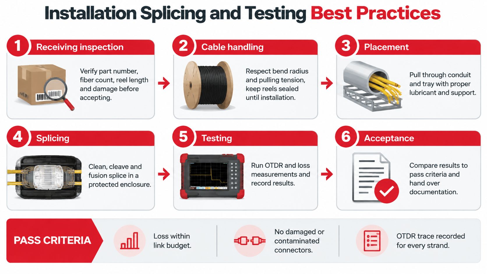
CommScope's fiber optics construction manual separates testing into shipping inspection, pre-installation, installation and final acceptance, with post-installation OTDR results compared against baseline measurements. That sequence is practical because it catches damage close to when it occurs and preserves a reference for later troubleshooting. For broader low-voltage installation context, see Access Electrical and Lighting's cabling guide.
1. Receiving inspection. Match the part number, fiber count, reel length and factory test data to the order. Photograph the reel tag and seal. Record any damage before the reel leaves the delivery point, when its condition is easiest to establish.
2. Pre-installation. Check duct condition, calculate pulling tension against the cable rating, and plan slack and closures around the cable's bend-radius limits. Include armor and handling constraints in the pull plan.
3. Installation. Use the specified lubricant and control tension throughout the pull. Keep force off armor edges, respect the cable's bend-radius class, and log pulling tension as the work proceeds. Reconstructed figures are weak evidence when a pull is disputed.
4. Splicing. Use individual fusion for loose-tube cable and mass fusion for ribbon. Protect each splice, dress it in the tray and record its loss on a worksheet linked to the fiber identification.
5. Testing. Measure insertion loss at the operating wavelengths: 1310 and 1550 nm for OS2, and 850 and 1300 nm for multimode. Verify multimode polarity. Capture bidirectional OTDR traces for every fiber and compare them with the factory baselines recorded at receiving.
6. Acceptance. Assemble reel records, splice worksheets, baseline and post-installation OTDR traces, power-meter results, and as-built or GIS documentation. Submit the package before final payment.
| Phase | Test or record | Pass evidence |
|---|---|---|
| Receiving | Part number, fiber count, reel length | Matches the order and factory test report for each reel |
| Installation | Pulling tension and bend radius at slack | Within cable limits, logged per pull |
| Splicing | Splice loss per fiber | Every splice recorded on a worksheet and protected |
| Testing | Insertion loss at operating wavelengths | Results recorded; polarity verified on multimode |
| Testing | Bidirectional OTDR compared with factory baseline | Results recorded for every fiber; the project specification sets the allowable mid-span attenuation increase per fiber against the factory baseline |
| Acceptance | Reel, splice, OTDR, power-meter and as-built records | Complete package filed before final payment |
A mid-span comparison is only useful when the factory baseline and field trace use consistent fiber identifiers and test conditions. Set the allowable attenuation increase per fiber in the project specification, then retain the measurements that demonstrate whether each fiber meets it.
If an accepted cable later shows attenuation drift, retrieve the stored baseline, run a fresh bidirectional trace, locate the event by distance, and compare it with the as-built splice and closure schedule. Record the fault response using the same identifiers. A documented event tied to a specific location gives the repair team a clear starting point.
The point that gets missed: “Installation complete” is not “network acceptance complete.” Baselines, bidirectional OTDR traces, splice records and traceability make the acceptance package a deliverable, not an afterthought.
Southern Tier Resources offers fiber optic splicing and testing services for projects that need that field scope. Keep the records tied to the acceptance requirements, whether the work is performed in-house or by a service provider.
Finalize Your Specification and Acceptance Plan
Three verdicts cover almost every case. Outside plant runs on OS2 loose-tube, moving to armored construction for direct burial and harsh routes. High-count trunk and metro duct work runs on ribbon for density and mass-fusion speed. Data halls run OM3 or OM4 for short links and OS2 wherever reach or a speed upgrade path demands it. None of those choices is complete without the acceptance plan that ships next to it.
The next step is a one-page specification listing the cable family, construction, fiber count, jacket rating, reel lengths, test wavelengths and acceptance thresholds, including a mid-span increase limit of no more than 0.1 dB per fiber. Attach the testing checklist from the installation section and the RFQ checklist from procurement, then send the same package to every bidder, distributor and turnkey contractor so each quote is priced against identical criteria.
That single page is what separates a cable purchase from a network you can prove. It also makes bid comparison honest, because every vendor is answering the same questions about materials, testing and documentation rather than presenting the reel price as the whole number.
Southern Tier Resources builds fiber networks end to end, from engineering and design through construction, splicing, testing and the as-built documentation that closes acceptance. If you're specifying CommScope fiber optic cable for a broadband, carrier or data center program, we deliver broadband fiber optic cable installation and the splice-and-test records your acceptance package depends on. Visit Southern Tier Resources to talk through your next build.