The Federal Communications Commission puts practical coverage for a small wireless facility at roughly 10 meters to several hundred meters, against macrocell footprints that stretch across tens of kilometers (FCC guidance on small wireless facilities). That gap of one to two orders of magnitude belongs at the top of every site plan, because it decides how many sites a market needs, how much fiber gets trenched, and how many permits a municipality will be asked to process.
Range isn't a number stamped on a radio. It's a planning result that falls out of transmit power, antenna height and downtilt, frequency, receiver sensitivity, interference limits, and whatever the street does to the signal between the antenna and the phone. A site that looks comfortable at 500 meters on a map can die at 180 meters on a dense block.
I treat every nominal radius as a ceiling the site has to earn, never a guarantee it receives. Start with the cell class the FCC describes, work through the propagation factors that move the number, and finish with the density and cost ledger that follows every choice you make.
Typical Small Cell Range by Cell Type and Band
The U.S. Federal Communications Commission defines small cells as low-power radio access nodes with coverage ranges from approximately 10 meters to 1 to 2 kilometers, depending on technology, frequency band, power level, antenna placement and the local propagation environment (FCC wireless infrastructure guidance). That's the honest answer to how far a small cell reaches, and it's honest precisely because it refuses to give one number.
Cell class decides where inside that span a site lands, and more usefully, which constraint bites first. The table below is the shorthand to scope a build before any propagation modeling happens.
| Cell class | Typical radius | Typical placement | Main limit |
|---|---|---|---|
| Femtocell (indoor) | 10-100 m | Rooms, floors, small buildings | Penetration loss and backhaul |
| Picocell | 100-500 m | Indoor hotspots, pole-mounted street nodes | Interference between neighbors |
| Outdoor microcell | 500-2,000 m (nominal) | Poles, rooftops, towers | Site count and transmit power |
| Rural extended cell | 1-2 km | Elevated masts | Terrain, foliage and backhaul distance |
| 28 GHz millimeter-wave street node | About 120 m | Lamp posts, building faces | Non-line-of-sight blockage |
Femtocells and picocells sit at the short end. A femtocell covers a room, a floor or a small building, and its real limit is penetration loss plus the backhaul available in that space. A picocell stretches a few hundred meters indoors or from a pole mount, and its limit is usually the neighbor, because two picocells close together compete for the same resources.
Outdoor microcells on poles, rooftops and water towers reach 500 to 2,000 meters nominal. Two things stop them short of that ceiling: the number of sites the operator can fund, and the transmit power a small pole-mounted unit can practically and legally deliver. Rural extended cells push to 1 to 2 km from taller masts, where terrain, foliage and the distance to the nearest backhaul handoff set the edge rather than the radio.
The millimeter-wave row is the shortest, and blockage does the limiting rather than power. That single fact explains why dense city builds use far more sites than free-space arithmetic would suggest.
Working rule: every radius in that table is a ceiling the site has to earn through height, siting and a clean RF path. None of them is a guarantee the hardware hands you.
The FCC notes that small cells mount on utility poles, streetlights, water towers and rooftops, which is how operators put radio equipment close to users and fill gaps a macrocell can't reach precisely. When you scope a build, find the row closest to your intended placement, write down its limiting factor, and carry that factor forward. A pole-mounted node planned at 500 meters and a rooftop node planned at 2 kilometers need different site counts, different backhaul and different permit strategies, even though both sit under the same small-cell definition.
What Sets the Real Radius of a Small Cell
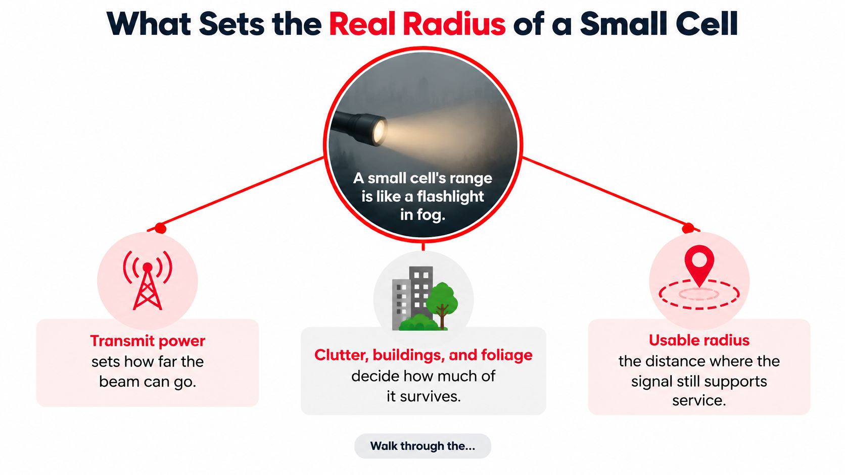
A small cell behaves like a flashlight in fog. Transmit power sets how far the beam can travel. The fog, meaning buildings, foliage and street clutter, decides how much of it survives to the phone. Usable radius is the distance where the surviving signal still supports the service you promised, and it's usually a good deal shorter than the beam's theoretical throw.
Five factors move that number, and they interact rather than stack neatly. Read the table as cause and effect, not as a checklist of independent settings.
| Factor | Typical change | Effect on radius | Planning action |
|---|---|---|---|
| Transmit power | Raise by 3 dB | Radius grows, but overlap and uplink imbalance worsen | Match power to the coverage target, not the maximum |
| Antenna height | Raise from 5 m to 10 m | Clears clutter and extends line-of-sight reach | Check pole loading and downtilt before raising |
| Frequency | Move from sub-6 GHz to 24-28 GHz | Radius shrinks and blockage dominates | Plan denser sites or redundant street nodes |
| Clutter and foliage | Dense buildings or tree canopy | Shadowed, irregular coverage inside the nominal radius | Run a site-specific RF prediction |
| Line of sight | Shift from LOS to NLOS | Path loss rises sharply | Add overlap at obstruction points |
Where each factor bites
Transmit power has the weakest return of the five. Another 3 dB adds 3 dB to the budget, which at a path-loss exponent around 3.5 buys well under a third more distance, while widening the coverage polygon into the neighboring site's territory. Uplink doesn't follow, because the handset's power is fixed, so a louder downlink produces an imbalanced link where the phone hears the tower and the tower struggles to hear the phone.
Antenna height does more per meter than power ever will in a street canyon. Moving a mast from 5 m to 10 m clears parked trucks, signage and pedestrian clutter and restores line of sight down the block. Check pole loading, wind loading and downtilt before raising anything, because a taller antenna aimed flat overshoots its own near field.
Frequency sets the floor. Moving from sub-6 GHz to 24 or 28 GHz shrinks the radius and makes blockage the dominant term, so the design shifts from power planning to obstruction planning.
Practical rule: if adding power changes your coverage map by more than a few percent, the site was never power-limited in the first place.
Clutter and foliage produce the irregular polygons that catch people out. A site with a clean geometric radius can still have a shadowed block behind a parking structure and a dead pocket under tree canopy, which is why a site-specific RF prediction beats a nominal radius every time.
Line of sight is the binary that matters most above about 6 GHz. A shift from LOS to NLOS raises path loss sharply, and the fix is overlap at known obstruction points rather than more power at the source.
A modeled result at 24 GHz
A representative 24 GHz small-cell model shows how far apart the theory and the usable answer sit. With the base station at 5 m and the user at 1.5 m, the calculated breakpoint distance is 640 meters, while the modeled average small-cell coverage radius comes out at approximately 56 meters (arXiv study of 5G small-cell coverage).
That ratio is the whole lesson in one scenario. Free-space geometry put the breakpoint hundreds of meters away, and the working radius landed at tens of meters because of everything standing between the radio and the phone.
Find the binding constraint before you touch power or height. On a clutter-limited site, more power only enlarges the overlap. On a height-limited site, a better mounting position does more than any setting in the radio's interface.
The Density Trade-off
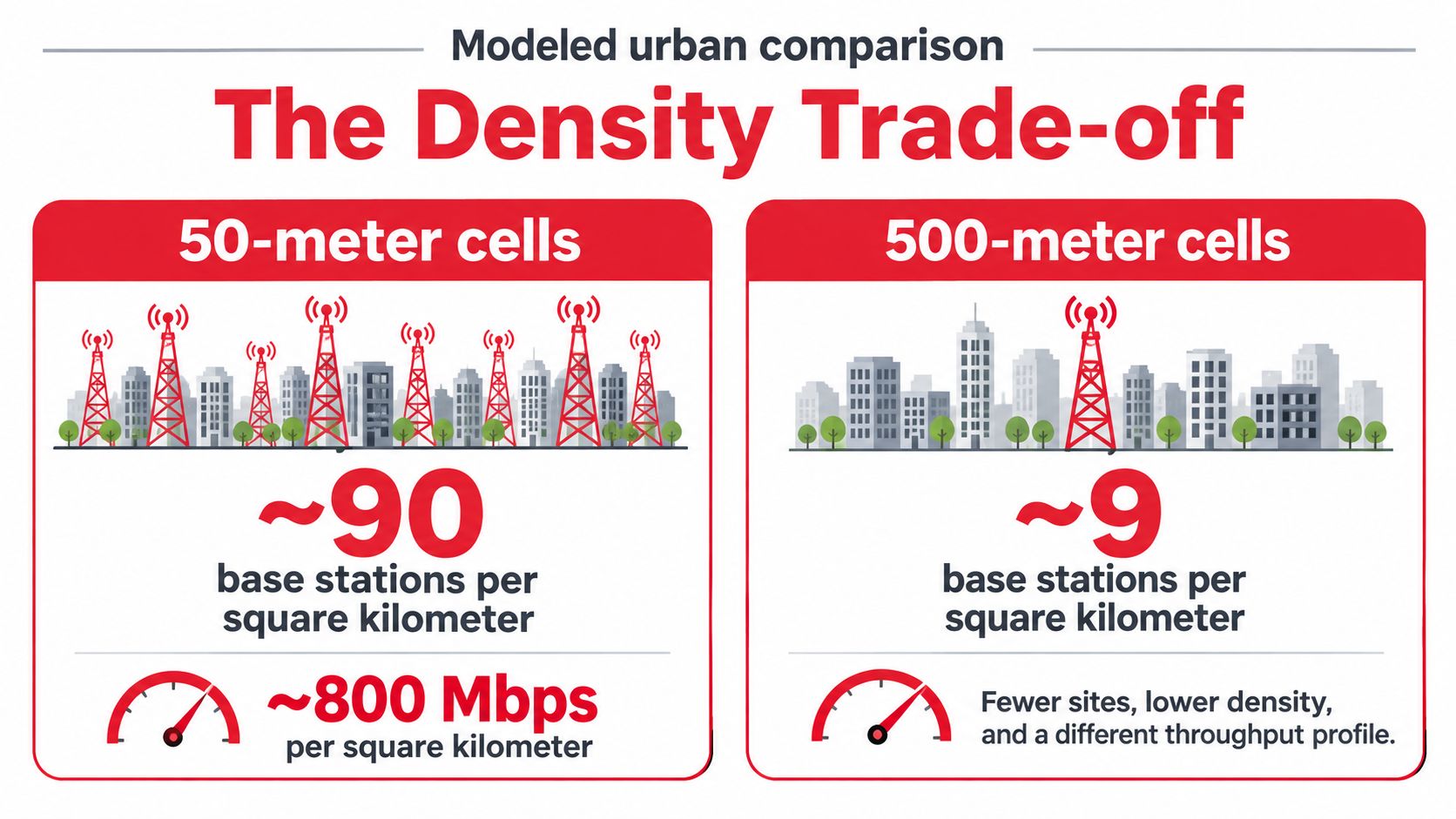
Put the two extremes side by side. A modeled urban comparison of 50-meter-radius cells required approximately 90 base stations per square kilometer and delivered roughly 800 Mbps per square kilometer. The 500-meter alternative needed about 4 base stations per square kilometer and delivered about 8 Mbps per square kilometer, a 100-fold gap in area capacity (published engineering evaluation of small-cell densification).
Why smaller cells carry more traffic
Every site reuses the same spectrum. Shrink the footprint and you fit far more non-interfering cells onto the same ground, which is how dense urban capacity gets built. Capacity per square kilometer climbs by an order of magnitude while coverage area per site collapses, and both halves of that sentence are true at once.
The same evaluation found signal quality falling steeply with distance, with simulated SINR dropping from 35 dB at 20 meters to 5 dB at the 150-meter cell edge, and identified a radius around 150 meters as the balance between infrastructure cost and performance. Scaling the 50-meter case by area puts a 150-meter grid near 10 sites per square kilometer and area capacity near 90 Mbps per square kilometer at the same per-site rate.
| Cell radius | Sites per km² | Area capacity | Main constraint |
|---|---|---|---|
| 50 m | About 90 | About 800 Mbps per km² | Highest fiber, power and permit load |
| 500 m | About 4 | About 8 Mbps per km² | Lowest site count, weakest spatial reuse |
| 150 m (planning balance) | About 10 | About 90 Mbps per km² | SINR falls from 35 dB at 20 m to 5 dB at the cell edge |
Millimeter-wave changes the arithmetic in a way that frustrates planners. For deployments around 28 GHz, non-line-of-sight propagation constrained coverage to roughly 120 meters, regardless of how many cells were deployed. Density buys capacity in that band, never reach.
The cost ledger: every extra site adds a fiber backhaul run, a power connection, a permit application and a maintenance visit. Density is a budget decision before it's a radio decision.
Treat these numbers as planning benchmarks rather than field guarantees, because they come from modeled scenarios. What travels between projects is the shape of the curve, not the decimal places.
Indoor and Outdoor Reach Are Not the Same Number
A small cell that reaches 500 meters down a street can still deliver weak service inside the building at the end of it. Measurements in urban office buildings found average penetration loss of approximately 12 to 13 dB with a 5 to 6 dB standard deviation, and ground floors performed worst in the reported environment (study of small-cell coverage range in urban buildings). Twelve decibels is roughly a sixteenth of the arriving power gone at the façade.
Three numbers people call range
- Outdoor reference-signal reach: the distance where the synchronization signal is still detectable on the street, which is what most published coverage claims describe.
- Indoor throughput and reliability: whether the link sustains the promised service inside a building on the second or third floor, after the façade takes its cut.
- Uplink coverage at the user: whether the handset can reach the site with enough margin, which usually fails before the downlink does because the phone transmits at a fraction of the site's power.
Quote a range at a defined service level, or don't quote one at all.
That third measure is where most surprises live. A phone indoors on a ground floor, behind a low-emissivity window, at the edge of the polygon, and transmitting uplink into a site designed around downlink coverage, is the user who files the complaint.
The better deliverable is a scenario-based range envelope rather than a single advertised radius. Run three: an unobstructed street with clean line of sight, a dense urban non-line-of-sight case with a defined overlap requirement between neighbors, and an indoor-floor case with a throughput floor attached. Each gets its own usable radius and its own acceptance threshold, and the envelope makes clear which one the sales claim refers to.
If indoor service is a stated target, plan indoor small cells or a distributed antenna system instead of stretching the outdoor radius. Adding power to reach through a wall also grows the overlap outside and worsens uplink imbalance, so you pay twice for the same weak result. Metal-clad buildings are the extreme case, where signal wraps the outside of the structure and drops off a cliff at the loading dock. If a site serves that kind of yard, treat exterior coverage as its own design problem and start with measures to improve signal outside metal buildings before adding another node.
How to Calculate and Validate a Usable Radius
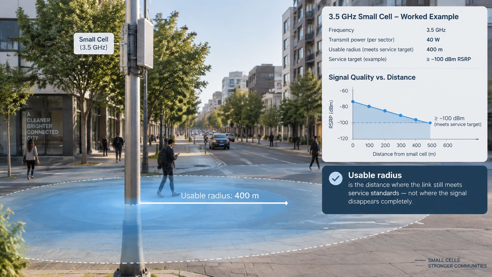
A usable radius is the distance at which a small cell still meets its service target. For a hypothetical 3.5 GHz street node, assume 40 dBm transmit power, 15 dBi antenna gain, 2 dB feeder loss, -100 dBm receiver sensitivity, and a 10 dB fade margin. The result is a planning estimate, not a guaranteed boundary: the model, service target, and surroundings determine whether that radius holds in the field.
- Set the service target. Specify the minimum received power and SINR at the cell edge, and define whether that edge is a street location or an indoor desk. An indoor target changes the link budget and may require a different site plan.
- Build the link budget. Add 40 dBm transmit power and 15 dBi antenna gain, then subtract 2 dB feeder loss. The result is 53 dBm EIRP, the effective radiated power used in the calculation.
- Subtract sensitivity and fade margin. With 53 dBm EIRP, -100 dBm receiver sensitivity, and a 10 dB fade margin, the maximum allowable path loss is 143 dB. The margin accounts for signal variation; reducing it can extend the calculated radius but leaves less room for real-world changes.
- Convert path loss to distance. Use a propagation model suited to the site environment, and record its path-loss exponent and breakpoint. A model intended for suburban macrocell planning can overstate street-level small-cell reach.
- Account for building loss. For an indoor target, subtract the expected façade loss before converting path loss to distance. The assumed loss should reflect the building and floor being served, rather than treating indoor reach as an extension of the outdoor radius.
- Compare with the expected range for the cell class and band. If the result is far outside the typical range, check antenna height, downtilt, frequency, and model assumptions before accepting it.
- Validate with drive or walk tests. Measure downlink and uplink, handover between neighboring nodes, and interference at intersections and building edges. Include locations near the predicted boundary, not only clear streets close to the site.
A modelled radius is a hypothesis until field measurements confirm it. Compare published coverage maps with drive or walk-test data from the same streets; finding a reliable NZ coverage map can help illustrate how mapped coverage edges differ from on-street measurements. Use those differences to refine the propagation assumptions and the usable-radius target. Each shorter target can require more sites, with added backhaul and permitting costs, so validate the radius before committing to locations.
Rural and Mid-Band Deployments Stretch the Radius
A small cell doesn't have to mean a short-range urban node. A 5G-PPP/Global5G study identifies rural small cells designed for extended coverage of typically 1 to 2 km, enabled by raised antennas and higher RF transmit power (Global5G.org study on small cells and dense cellular networks). The same analysis reports that sub-6 GHz represented 73.20% of small-cell 5G shipments in 2025, because it balances propagation against capacity.
Extending the radius spends the densification advantage. Once a rural node reaches a couple of kilometers, terrain, foliage, backhaul availability, power and site elevation decide feasibility as much as the radio specification does. A mast on the wrong side of a ridge with no fiber within reach is a worse investment than two well-sited nodes on the road side.
Spectrum choice moves the radius
Higher-frequency bands deliver capacity but generally require tighter site spacing, which is why coverage-led builds stay on mid-band even when the marketing pushes millimeter wave. The spectrum decision sets the site count before the RF design begins, and reversing it later means rebuilding the plan.
Decision rule: choose an extended rural cell when area covered per site matters more than capacity per square kilometer, and a mid-band dense layout when capacity drives the design.
Shared infrastructure complicates the picture in a useful way. Neutral-host deployments serve multiple operators from one layout, which cuts the physical site count and the visual clutter. Overlapping dense deployments built separately by several operators and neutral hosts, on the same streets, tend to become commercially and environmentally unsustainable. If you're a municipality or a utility cooperative planning a corridor, the question to answer isn't how far one cell reaches. It's the least-cost site density that meets coverage, capacity and multi-operator requirements in that specific environment.
Deployment Scenarios for Carriers, ISPs and Integrators
The same radius target plays out differently depending on who's building. Three builds, read in the same order: radius target, binding limit, site density, backhaul route, acceptance test.
Carrier street layer in a dense city
The target is capacity in a small footprint at millimeter wave, and the binding limit is blockage rather than power. That flips the site list: it gets built from obstruction points and fiber routes, not from a uniform grid. Density is high and dictated by where line of sight survives. The acceptance test is a walk test at the likely obstruction points, at intersections and behind street furniture.
ISP fixed-wireless rural coverage
Here the target is area per site, so a taller mast on mid-band is the right tool, and terrain plus backhaul distance become the binding limits. One good site replaces many urban nodes, but the route to backhaul decides whether the site is viable at all. Survey the path before surveying the tower. Acceptance means uplink testing at the far edge of the intended service area, where the handset's power runs out first.
Integrator indoor office build
Indoor, the target is throughput per floor and the femtocell or distributed antenna classes apply. Ground-floor and basement positions carry the heaviest penetration loss, and no outdoor node substitutes for an indoor one. The site list runs vertically, one per floor or zone, with backhaul on building Ethernet or fiber. Acceptance is a walk test on the worst floor with the doors closed.
Record all five fields for every scenario in one table before design starts. The comparisons stay honest that way.
Set the Radius Target Before You Commit to Sites
Small-cell radius is a deployment choice, not a guaranteed coverage boundary. Set the target before building the site list: it determines how many locations need fiber, power, permits and ongoing maintenance.
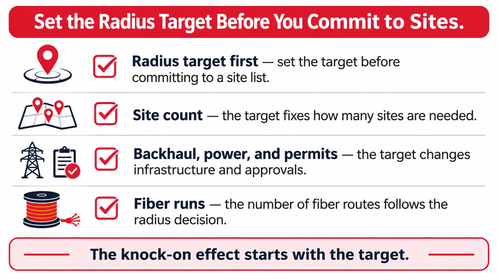
The knock-on effect of a radius decision
For a roughly uniform coverage area, halving the target radius can require about four times as many sites. That means more construction, utility coordination and maintenance, even when the radio hardware stays the same. A dense urban grid and a sparse deployment are different projects in cost and permitting, as well as coverage.
Before approving locations, work through this checklist:
- Set the target class and radius using the typical ranges in this guide. Record both in the design brief, with the understanding that obstructions and indoor losses can reduce usable reach.
- Identify the limiting condition at each candidate site, such as height, clutter or line of sight. The constraint shapes the practical coverage area.
- Check backhaul feasibility at each location. Fiber or wireless backhaul must support the site; without a viable route, the location cannot serve its intended role.
- Confirm power and structural capacity for each pole or tower, including applicable wind and ice loading requirements.
- Understand the permit path for street or rooftop placement, including any required pole-attachment agreements.
- Define acceptance testing before construction, including drive or walk tests and checks at intersections and building edges.
Use the target radius to compare candidate sites against the actual build constraints. A longer outdoor reach may reduce site count, but it does not guarantee indoor service, and each added site brings construction and ongoing maintenance costs.
Southern Tier Resources provides turnkey wireless deployment, along with engineering, design, construction and maintenance for wireline and wireless communications. Bring your coverage objective to Southern Tier Resources to discuss the infrastructure needs of your deployment.