You're responsible for a stadium, hospital, airport, or office tower where users complain about dropped calls even though their phones show a signal. The problem may not be the carrier network outside. Concrete, steel, low-emissivity glass, vertical separation, and crowded indoor zones can all turn a usable macro signal into poor indoor service.
A distributed antenna system, or DAS, treats that problem as an infrastructure design challenge rather than a coverage patch. It distributes many lower-power antenna nodes throughout a building or campus, connects them to a shared head-end, and uses fiber, coax, or both to deliver carrier signals where users need them. The important question isn't whether DAS works. It's whether a passive, active, hybrid, small-cell, or Wi-Fi-assisted design matches the building's density, carrier mix, fiber pathways, public-safety obligations, and long-term ownership model.
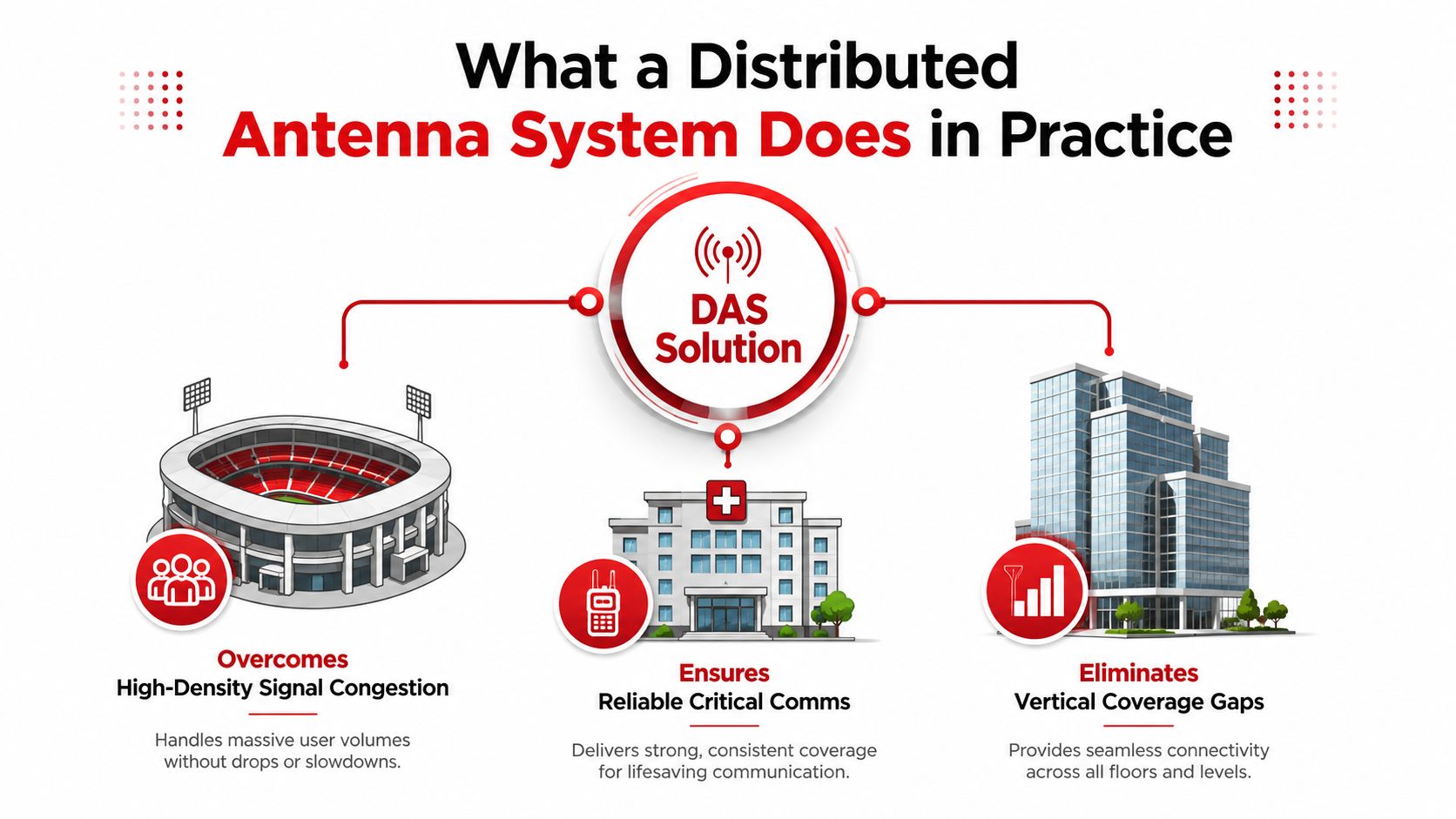
What a Distributed Antenna System Does in Practice
A packed stadium concourse is a useful example. Thousands of people may be trying to call, message, stream, scan tickets, or access cloud applications while surrounded by concrete structure and multiple levels of enclosed space. A single rooftop antenna or indoor booster might improve the signal level in part of the concourse, but it won't necessarily provide the capacity, control, and multi-carrier behavior that the venue needs.
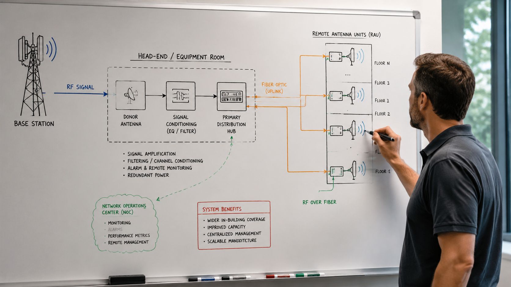
A DAS uses a network of spatially separated antennas connected to a common signal source. The signal may come from a carrier base station, an off-air donor, or an on-premises small cell. A central head-end receives and conditions those signals, then distributes them through fiber, coaxial cable, or a hybrid transport network to remote units and antenna nodes.
The signal path
The practical sequence looks like this:
- A signal source enters the system. Carrier equipment, a donor antenna, or a small-cell source supplies the radio signal.
- The head-end conditions the signal. Filters, combiners, interface equipment, and monitoring systems prepare multiple bands or operators for distribution.
- Transport carries the signal through the facility. Fiber handles long backbone runs, while coax can serve shorter local antenna branches.
- Remote units convert and amplify the signal. Active remotes turn optical or digital transport back into RF near the coverage zone.
- Distributed antennas serve devices locally. Ceiling omnis, panel antennas, or directional antennas create controlled coverage instead of forcing one distant source through the building.
That makes DAS different from a consumer signal booster or simple repeater. A booster may retransmit a donor signal, but a carrier-grade DAS is engineered around coverage maps, interference control, sectorization, carrier interfaces, and acceptance testing. It can be designed for several operators and frequency bands on one shared physical plant.
Coverage and capacity also need separate treatment. A building can have adequate signal strength and still deliver poor service because too many users share limited radio resources. Selective transmission is particularly important here. A peer-reviewed analysis found that selective transmission outperformed blanket transmission in regular DAS, while a user-centric DAS with selective transmission achieved the highest average spectral efficiency among the compared schemes (technical DAS analysis).
Practical rule: Design the antenna network around where users concentrate, not just where a heat map shows weak signal.
Passive, Active, Hybrid, and Small-Cell Architectures Compared
The architecture choice determines more than equipment cost. It affects cable pathways, power requirements, carrier onboarding, expansion options, and how painful the next renovation will be.
Passive DAS keeps the RF signal in coaxial cable and distributes it with splitters, couplers, and passive antennas. It has fewer powered elements and can be economical in a compact building with short runs. The trade-off is accumulated cable and splitter loss. Long risers, large floor plates, and multiple bands can make a passive design difficult to balance.
Active DAS converts RF into optical or digital transport at the head-end, sends it over fiber to remote units, and converts it back near the antennas. Fiber supports long distributed runs and gives engineers more control over power and zoning. Airports, stadiums, hospitals, and large campuses often justify the added equipment because the system needs distance, scalability, and multi-carrier support.
Hybrid DAS uses fiber for the backbone and coax for the local antenna distribution. It avoids placing a powered remote at every antenna position while preserving a fiber-fed path across floors or buildings. This is often a practical middle ground for commercial properties where a fully passive riser is too lossy and a fully active design adds unnecessary complexity.
Small-cell-integrated designs use operator-owned or neutral-host small cells as the signal source instead of relying primarily on a macro donor. They can be a better fit for a smaller enterprise building with a defined carrier requirement, especially when the owner needs capacity in a particular zone rather than broad multi-operator infrastructure.
| Architecture | Transport | Distance Limit | Best-Fit Venue |
|---|---|---|---|
| Passive DAS | Coax, splitters, and couplers | Shorter runs, with loss accumulating along the path | Compact offices, smaller commercial buildings, and limited footprints |
| Active DAS | Fiber to powered remote units, then RF to antennas | Long backbone runs across buildings or campuses | Airports, hospitals, stadiums, and dense multi-storey properties |
| Hybrid DAS | Fiber backbone with coaxial local distribution | Longer backbone reach with shorter coax branches | Mid-size offices, hotels, and commercial buildings |
| Small-cell-integrated design | Ethernet or fiber to small-cell sources and local RF distribution | Dependent on the small-cell and distribution design | Smaller enterprise venues with focused carrier or capacity needs |
There isn't a universal “best” DAS architecture. A passive system may be the right engineering answer for a compact office, while the same approach becomes a costly compromise in a high-rise with multiple carriers. An active system can solve distance and capacity problems, but it brings powered remote units, equipment rooms, battery considerations, monitoring, and maintenance into the ownership discussion.
The market direction supports that nuance. One industry estimate values the global DAS market at USD 9.7 billion in 2023 and projects USD 13.0 billion by 2028, a 6.2% CAGR, while another forecast places the U.S. market at USD 2,247.8 million in 2024 and USD 5,622.4 million by 2030, implying a 17.1% CAGR from 2025 to 2030 (MarketsandMarkets DAS market data). Those forecasts describe a growing category, not a reason to specify active DAS everywhere.
Inside the Head-End, Remotes, and Fiber Backhaul
On a whiteboard, a field engineer usually draws the system from left to right. The carrier base station hotel, small-cell source, or off-air donor sits at the beginning. The head-end follows, then the fiber backbone, remote units, antennas, and finally the user device.
What each component does
The head-end is the control and aggregation point. It receives carrier inputs, filters unwanted energy, combines supported bands or operators, and manages the conversion between RF and optical or digital transport. It also hosts alarms and monitoring interfaces that let operators identify faults without sending a technician to every antenna.
The fiber backbone carries the signal from the head-end to remote units. Single-mode fiber is common for long distribution paths, but the design still depends on pathway availability, splice quality, connector cleanliness, labeling, and separation from other building systems. A fiber route that looks available on a drawing may be inaccessible once walls, ceilings, firestopping, and tenant finishes are accounted for.
Remote units normally sit in telecom rooms, riser spaces, or protected overhead locations. Each remote feeds a cluster of antennas. Ceiling-mounted omnidirectional antennas work well in open areas, while panel antennas can control energy along corridors, stairwells, tunnels, or narrow floor plates. The antenna type and location affect both usable coverage and interference between zones.
Monitoring often shares the same structured infrastructure or riser strategy. Ethernet connectivity can carry management traffic and SNMP alarms, while the RF path remains on fiber and coax. That separation helps the operations team distinguish a carrier input problem from a failed remote, a fiber fault, or a local power issue.
Where installations go wrong
Most commissioning surprises aren't mysterious RF phenomena. They're construction and integration failures:
- Fiber damage: Other trades crush, cut, or bend fiber during ceiling and riser work.
- Poor identification: Crews terminate or label fiber pairs inconsistently, slowing testing and carrier integration.
- Head-end oversights: Designers underestimate rack space, electrical service, grounding, battery backup, HVAC, or access requirements.
- Unprotected equipment: Remotes installed without proper environmental or mechanical protection fail before the radio design reaches its intended life.
A DAS head-end is a small technical facility, not just another rack in the MDF.
Treating the head-end as building infrastructure from the first design review prevents late changes to power, cooling, fire protection, and physical access.
Coverage, Capacity, and RF Planning Decisions
A DAS that “lights up” a building can still fail during the busiest operating period. Engineers need to separate coverage, which answers whether the device can reach the network, from capacity, which answers whether the network can serve the users sharing that radio resource.
Coverage planning starts with link budgets and path-loss modeling. Engineers account for cable and component loss, antenna gain, building penetration, floor separation, and the expected device location. Concrete, steel, low-emissivity glass, elevator shafts, stairwells, and below-grade rooms all change the result. Ceiling omnis can distribute energy broadly across open floor plates, while directional panels can control coverage in long corridors or targeted zones.
Capacity needs spatial planning
Capacity depends on user density, traffic behavior, available spectrum, sectorization, MIMO configuration, and the interference environment. Reuse distance is one of the most important levers in multi-storey buildings. A conference study reported that indoor DAS produced nearly a 1 bit/s/Hz increase in achievable rate over an indoor small-cell baseline at a reuse distance of one floor, with much larger gains when reuse distance increased to two floors (indoor DAS reuse study).
The same principle can create a difficult trade-off. Increasing separation between reused resources can reduce co-channel interference, but it may also limit how aggressively the system reuses spectrum. Engineers model floor-to-floor leakage, antenna power, wall losses, and user distribution rather than choosing a reuse pattern by rule of thumb.
Band strategy changes the plant
Low-band spectrum generally helps coverage and penetration. Mid-band spectrum contributes capacity, while higher 5G bands can support densification in carefully planned zones. Adding bands increases the burden on combiners, filters, remote-unit capacity, antenna compatibility, cable loss, and head-end space. A design that supports more bands isn't automatically more future-proof if the owner can't fund or maintain the associated hardware.
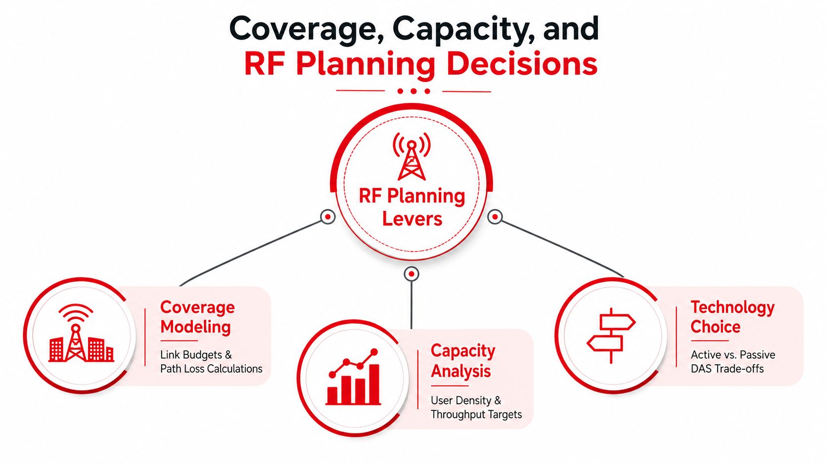
A useful design package should show predicted users by zone, throughput targets, uplink noise rise, handoff boundaries, and the expected performance of each supported band. If the model shows that only a limited area needs additional capacity, small cells or Wi-Fi offload may be more rational than expanding the entire DAS.
Peer-reviewed work also supports selective transmission as an efficiency tool. Serving users from nearby antenna nodes under favorable channel conditions can improve spectral efficiency compared with transmitting broadly across every node (selective-transmission DAS research). The practical outcome is a zoned design that uses radio resources deliberately instead of broadcasting every signal everywhere.
From Site Survey to Commissioning on a Real Build
A real multi-carrier DAS project starts with evidence, not a brand selection. The survey team walks the facility, captures the existing RF environment, checks target areas, and audits the infrastructure that will carry the system. A useful Splash Access site survey guide provides helpful context for the assessment discipline involved.
The deployment sequence
Phase one is field discovery. Engineers use walk-testing, spectrum capture, floor plans, and an infrastructure audit. They verify MDF and IDF locations, riser capacity, fiber pathways, ceiling access, equipment-room conditions, structural mounting points, and authority-having-jurisdiction requirements.
Phase two turns the survey into a buildable design. An iBwave model can establish antenna locations, cable routes, remote zones, head-end layout, bill of materials, and predicted RF performance. Carrier coordination then begins. Each operator may review the RF design, source requirements, supported bands, alarm interfaces, and acceptance criteria before approving the system.
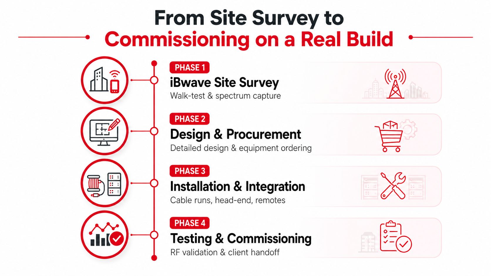
Phase three covers permits and construction readiness. Structural review, electrical design, firestopping, grounding, and public-safety requirements can all affect the route. Public-safety ERRCS work may require a separate review path and coordination with local code officials, especially where an overlay must operate alongside commercial cellular service.
Phase four is installation, integration, and acceptance. Crews pull and test fiber, terminate coax, mount antennas and remotes, build the head-end, connect power and monitoring, and complete carrier-by-carrier optimization. RF validation commonly includes PIM testing, sweep testing, continuous-wave checks, alarm verification, and ATP documentation.
The schedule usually slips at interfaces. Carrier implementation teams have approval queues. Finished ceilings hide pathway conflicts. A fiber route may require redesign after construction begins. Commissioning windows can also depend on carrier personnel and live-network access, so a physically complete system may still wait for final acceptance.
Reserve time for documentation and remediation. As-built drawings, fiber test results, antenna identifiers, power records, alarm lists, and carrier sign-offs should be treated as deliverables, not paperwork added after the system is already in service.
ROI, Neutral-Host Economics, and Lifecycle Costs
DAS economics begin with ownership, not the equipment quote. The capital budget can include the head-end room, fiber backbone, remote units, antennas, combiners, carrier interfaces, racks, power, grounding, and construction. Design, permitting, carrier coordination, structural review, project management, testing, and documentation can materially change the final investment because the system is integrated into the building rather than installed as a standalone appliance.
Operating costs continue after acceptance. Active remotes and head-end equipment need monitoring, preventive maintenance, software support, battery testing, replacement planning, and a suitable environment for power and cooling. Fiber and passive components have different maintenance profiles, but neither is cost-free when pathways are difficult to access or tenants occupy the surrounding space.
Neutral host versus single-carrier funding
A single-carrier build can be straightforward when one operator has a clear coverage obligation and agrees to fund the required infrastructure. The owner, however, may face limited support for other carriers and may need a second system later.
A neutral host changes the commercial structure. A third party funds or manages shared infrastructure, then brings multiple operators onto the platform through separate agreements. That can spread capital across participating carriers and create a lease or revenue model for the property owner, but it also adds negotiation, technical onboarding, and governance requirements.
| Model | Capital Source | Typical CAPEX per Sq Ft | Carrier Onboarding | Owner Risk |
|---|---|---|---|---|
| Single-carrier funded build | One mobile operator or shared agreement | Project-specific, not a universal benchmark | Limited to the funding carrier's process | Future carrier coverage may require a new agreement or expansion |
| Owner-funded DAS | Building owner or enterprise | Project-specific and dependent on architecture | Owner coordinates each carrier | Owner carries capital, performance, and lifecycle responsibility |
| Neutral-host DAS | Neutral host with carrier participation | Project-specific, often structured around shared infrastructure | Multiple operator agreements and technical approvals | Commercial utilization and lease terms affect return |
| Small-cell service model | Service provider or operator | Project-specific, based on radios, transport, and service terms | Focused on participating operators | Contract dependence and service fees replace some upfront capital |
The right comparison isn't just DAS versus small cells. It's the total cost of providing required coverage and capacity over the building's operating life. Buyers should model cost per covered area, cost per supported band, head-end power and cooling, access for maintenance, expansion capacity, and the consequences of adding another carrier.
Market forecasts show how varied the estimates can be. One report projects the DAS category from USD 10.91 billion in 2025 to USD 14.72 billion by 2031, while another describes estimates ranging from USD 12 billion in 2026 to USD 20.1 billion by 2031 and USD 30.7 billion by 2035 (Mordor Intelligence DAS market coverage, Global Market Insights DAS analysis). The spread reinforces a practical point: owners should trust a site-specific lifecycle model more than a headline market forecast.
Where DAS Wins and How Operators Deploy It
DAS remains strongest where many users, difficult construction, several carriers, and public-safety requirements intersect. Commercial properties represented 87.1% of overall DAS demand in 2022, according to a market study (Grand View Research DAS market analysis). That concentration reflects how the technology is used in enterprise buildings and major public venues rather than ordinary residential deployments.
| Venue | Recommended Architecture | Primary Driver |
|---|---|---|
| International airport terminal | Neutral-host active DAS | Multi-carrier roaming, long pathways, dense passenger zones |
| Hospital campus | Active or hybrid DAS with public-safety overlay | Reliable commercial and responder communications across complex construction |
| Stadium | Active DAS with careful sectorization | High event density and localized capacity demand |
| Corporate campus | Hybrid DAS or coordinated small cells | Shared fiber, building variation, and controlled user zones |
| Data center | Targeted small-cell or hybrid design | Operational coverage, security, and limited tolerance for unnecessary RF complexity |
| Transit hub | Active DAS or neutral-host architecture | Tunnels, platforms, handoffs, and multi-operator service |
An international terminal typically needs a neutral-host model because travelers arrive with different operators and the owner can't design around one carrier. A suburban office park may need less. If the buildings have usable fiber, moderate density, and a defined carrier set, a hybrid small-cell-integrated approach can avoid the cost of distributing a full active DAS everywhere.
Hospitals add another layer. Engineers must coordinate commercial cellular coverage with public-safety radio requirements, protected areas, generator-backed systems, and clinical operations. Stadiums require capacity models that reflect bowl seating, concourses, suites, loading areas, and event-day traffic patterns rather than average occupancy.
Campuses benefit when the wireless design aligns with existing fiber and macro coordination. A shared backbone can connect multiple buildings, but the radio architecture still needs to respect each structure's materials, user density, and carrier requirements.
For a compact retail rollout, a project such as the Sprint Stores CCT Wireless project offers useful context for how wireless construction can be delivered across distributed sites. The broader lesson is that repeatable deployment standards matter when the footprint includes many locations with different pathways and site conditions.
Southern Tier Resources can fit into this delivery model as an infrastructure contractor supporting engineering, fiber, construction, testing, and maintenance across wireless programs. The owner still needs to define the commercial model and carrier commitments before selecting the physical architecture.
Choosing the Right Architecture for Your Venue
“Just add DAS” is often an expensive way to avoid diagnosing the problem. Start by identifying whether the failure is coverage, capacity, mobility, public safety, or carrier availability. A low signal level in a basement needs a different intervention from a strong signal that collapses during a crowded event.
Use this decision checklist:
- User density: Map where people gather and how traffic changes during peak operations.
- Carrier mix: Decide whether one operator is enough or whether the building needs a neutral-host platform.
- Fiber availability: Confirm riser routes, splice locations, room space, and pathway access before choosing active remotes.
- Building size and geometry: Short, compact cable runs may favor passive distribution, while long risers and multiple structures favor fiber-fed designs.
- Public-safety obligations: Treat ERRCS or other responder-radio requirements as a separate compliance and engineering workstream.
- Offload options: Check whether managed Wi-Fi can carry appropriate enterprise traffic, while recognizing that it won't replace licensed cellular service for every user or application.
- Expansion needs: Leave room for additional bands, carriers, zones, and monitoring without assuming every future requirement belongs on the first build.
A passive DAS can be sufficient in a compact mid-rise office with manageable cable lengths and limited carrier requirements. A hospital, stadium, airport, or large campus usually needs active or hybrid architecture because distance, density, and operational consequences raise the design threshold. Small cells may be the more honest answer when the problem is localized capacity, the carrier mix is narrow, and the owner doesn't need a shared multi-operator plant.
Red flags for over-specification include a small footprint with short pathways, low and predictable user density, strong existing coverage, no multi-carrier requirement, and a solution driven mainly by a desire for “future-proofing” without a funded expansion plan. In those cases, targeted small cells, Wi-Fi offload, or temporary coverage equipment may solve the actual problem faster and with less lifecycle burden.
Southern Tier Resources supports wireless infrastructure projects that require coordinated engineering, fiber construction, installation, testing, and maintenance across DAS and small-cell environments. If you're evaluating a venue or campus, visit Southern Tier Resources to discuss the site conditions, carrier requirements, and delivery model before committing to an architecture.