The racks are installed, the UPS is energized, cooling is running, carrier circuits are lit, and the access-control panels show green. The project still isn't ready if nobody can prove which power path feeds each cabinet, whether the cooling response has been tested at design density, which fiber links passed certification, or whether operators received current as-built drawings.
A useful data center infrastructure requirements checklist follows the facility from design through acceptance and handoff. It assigns every requirement an owner, a verification method, a maintenance responsibility, and a document that operations can trust. That approach catches hidden dependencies before they become outages, unsafe workarounds, or expensive rework.
The checklist below is organized around failure prevention, serviceability, scalability, and evidence. Southern Tier Resources can support the physical work behind that evidence, including structured cabling, fiber installation and testing, fit-out execution, and as-built documentation. The result should be more than a room full of equipment. It should be an operational system that the next team can inspect, maintain, expand, and troubleshoot with confidence.
1. Power Distribution and UPS Systems
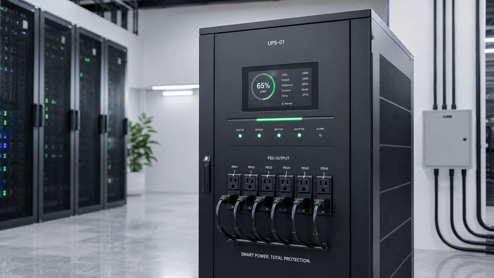
Power design starts with the utility interface and ends at the cabinet receptacle. Review primary service capacity, utility agreements, switchgear, transformers, distribution paths, UPS modules, batteries, generators, fuel systems, automatic transfer equipment, grounding, bonding, and monitoring as one chain. A redundant component doesn't protect the load if both paths share an overlooked breaker, busway, room, or utility dependency.
The reliability target must drive the topology. Uptime Institute's model places Tier III at 99.982% expected uptime, or about 1.6 hours of downtime per year, and Tier IV at 99.995%, or about 0.4 hours per year. Those benchmarks explain why a serious design review asks whether operators can maintain equipment without interrupting the critical load, not merely whether the equipment exists. Uptime Institute tier benchmarks and power guidance provides useful context for translating availability goals into power-path decisions.
Practical rule: A one-line diagram isn't acceptance evidence. The commissioning record must show that each intended path carried its designed load and that failover behaved as documented.
Verify the handoff
Require load-bank testing, UPS battery health records, generator start and transfer results, alarm verification, and updated circuit schedules. Install monitoring at facility, row, cabinet, and critical distribution levels so operators can identify imbalance or declining capacity before a trip.
Southern Tier Resources can help coordinate fit-out activities, cable pathways, labeling, testing, and the documentation that connects field installation to the final power and connectivity record. Keep preventive maintenance windows aligned with low-risk operating periods, and retain every test result with the as-built package. Teams planning efficiency improvements can also use these electricity consumption reduction tips when reviewing operating practices.
2. Cooling and Environmental Control Systems
Cooling should be designed from the rack outward, not selected after the room layout is complete. Model airflow, heat rejection, humidity control, equipment clearances, maintenance access, and failure response under the actual deployment profile. Traditional air cooling may be workable for moderate loads, but high-density AI and GPU zones can exceed 40–60 kW per rack and may require direct-to-chip liquid cooling or another advanced heat-rejection method, according to Uptime Institute's 2025 annual survey.
Containment can improve predictability, but it won't solve an undersized plant or blocked return path. Place sensors at multiple rack heights, validate supply and return behavior with thermal imaging, and preserve service clearances around computer room air handlers, pumps, heat exchangers, and liquid-cooling distribution units.
Treat water and heat rejection as site constraints
Air, liquid, evaporative, and hybrid approaches carry different maintenance, water, leak, and retrofit implications. Knight Frank's 2025 global data center report emphasizes the specialized infrastructure required for data centers, including advanced cooling and reinforced floors. Site reviews should therefore test water availability, discharge requirements, local environmental obligations, and the building's ability to accept future liquid-cooling infrastructure.
Commissioning should include staged thermal testing, alarm checks, control-sequence verification, and documented recovery from a cooling-unit failure. Efficiency tracking can use PUE, with current benchmarking guidance identifying values below 1.4 as efficient in current reporting frameworks. The same guidance uses kW per ton to compare cooling-plant performance and identify retrofit priorities.
The rack aisle shown below illustrates why equipment placement, containment, and maintainable airflow must be reviewed together.
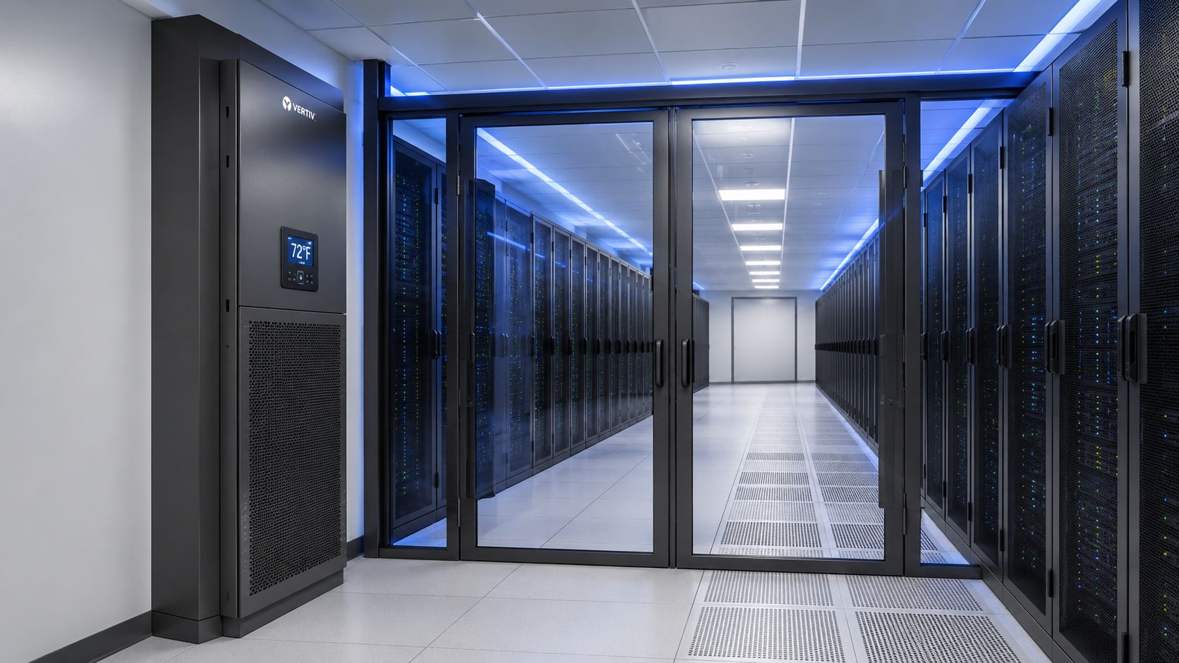
A visual walkthrough can help teams discuss airflow, clearances, and service access before commissioning begins.
3. Structured Cabling Infrastructure and Network Connectivity
A reliable network depends on the physical layer being easy to identify, test, expand, and repair. Define entrance facilities, meet-me rooms, carrier pathways, distribution frames, patch panels, overhead or underfloor routing, copper and fiber types, pathway separation, slack storage, labeling, and cross-connect ownership before installation begins.
The design must support both current protocols and future changes without turning every expansion into a demolition project. Fiber-to-the-rack can support higher bandwidth and simplify migration, while diverse carrier entrances and physically separated pathways reduce the chance that a single construction event removes every route. Keep bend-radius requirements, connector cleaning, polarity, splice records, and patching conventions in the installation standard.
Make certification part of acceptance
A cable is not complete because light reaches the far end. Require visual inspection, polarity verification, insertion-loss testing, optical time-domain reflectometer traces where appropriate, copper certification, end-to-end labeling, and a report tied to each link identifier. Photograph congested or concealed pathways before closure, and update topology drawings when field routing differs from the design.
Southern Tier Resources can support fiber-optic deployment, structured cabling, splicing, testing, and the as-built records needed for operational handoff. Build spare pathway and panel capacity into the design, but don't treat spare capacity as permission for poor routing. Unused space must remain accessible, labeled, and protected from accidental damage.
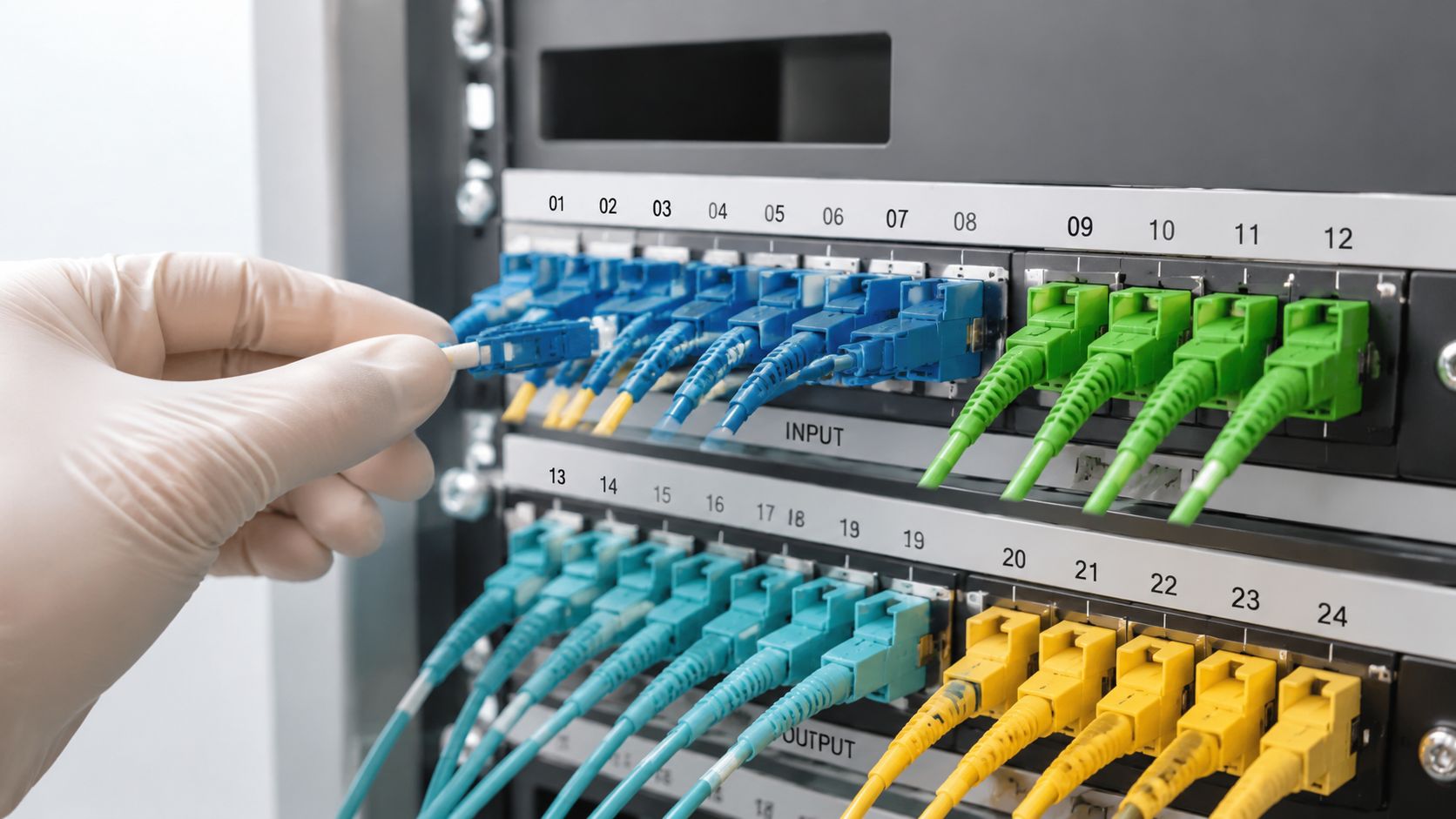
A future connection is only useful if an operator can locate its pathway, identify its termination, verify its test record, and add it without disturbing live services.
4. Fire Detection and Suppression Systems
Fire protection must protect people first, then limit damage to equipment and service continuity. Review detection, alarm annunciation, suppression, zoning, pre-action water systems, clean-agent options, room integrity, emergency power, release controls, and coordination with the authority having jurisdiction. The right design depends on room construction, occupancy, equipment arrangement, environmental conditions, and applicable code requirements.
Detection should provide layered coverage rather than relying on one sensor type. Early-warning aspirating detection can complement point sensors, while visual detection may help in spaces where smoke movement or visibility makes conventional detection less predictable. Suppression zones should align with actual infrastructure boundaries, not merely architectural room lines.
Prove the alarm sequence
Acceptance testing should confirm detector operation, alarm annunciation, notification appliances, shutdown sequences, door and damper behavior, suppression release logic, manual abort functions, supervisory signals, and monitoring-center communication. Record the results by zone, including any devices that were inaccessible or excluded from the test.
Clean agents such as FM-200 or Novec 1230 may reduce the risk of water damage to electronics, but they introduce enclosure-integrity, agent-management, personnel-safety, and regulatory considerations. A water-based or hybrid system may be appropriate in another area. The design team must document why the selected approach fits the hazard.
Train staff on evacuation, alarm response, impairment procedures, and re-entry controls. Coordinate inspection records and emergency contacts with the local fire department. For a broader regional review, consult this Queensland fire protection guide, then confirm the requirements that apply to the project's actual jurisdiction.
5. Network Security and Access Control
Security has a physical layer, a network layer, and an operating process. Start with the perimeter, reception, mantraps, cages, cabinets, keys, badges, biometrics, cameras, visitor handling, and vendor access. Then map logical segmentation, firewall boundaries, administrative interfaces, out-of-band management, monitoring, and incident response to the same zones.
Progressive access is easier to audit than broad access. A contractor may need a defined pathway or cabinet for a limited task, but that shouldn't grant unrestricted entry to the meet-me room, control systems, or customer areas. Time-limited credentials, escort rules, work orders, and automatic access expiration reduce the risk created by temporary work.
Connect access events to response
Keep access logs, camera retention requirements, alarm records, and network events available to the teams responsible for investigation. Review anomalies rather than collecting logs that nobody can interpret. Security staff and network operators should know who owns escalation when a badge event, cabinet opening, port change, or unusual traffic pattern appears at the same time.
Zero-trust principles are useful here because they require identity and authorization at each relevant layer. They don't replace physical barriers, segmentation, patching, or tested response procedures. During acceptance, test denied access, forced-door alarms, camera coverage, badge revocation, firewall rules, intrusion alerts, and vendor credential expiration.
Document the zone map in the handoff package. Include access-control points, camera views, network boundaries, responsible owners, and emergency overrides. Operators need a current record that supports both routine maintenance and incident response.
6. Monitoring and Management Systems
A facility without usable telemetry makes operators wait for symptoms. Monitoring should cover power quality, breaker state, UPS condition, generator status, fuel, temperature, humidity, airflow, leak detection, cooling controls, network equipment, access events, fire alarms, and environmental conditions. DCIM platforms, building-management systems, network-management tools, and security platforms may remain separate, but their ownership and escalation paths must be clear.
Configure monitoring during commissioning, not after the first incident. Establish normal operating baselines under representative conditions, then set alert thresholds that reflect equipment limits, operating procedures, and the time required to respond. An alarm that fires constantly teaches operators to ignore alarms. A threshold set too close to failure gives the team no usable response window.
Build dashboards for decisions
Operators need actionable views by room, row, system, and alarm severity. Facilities managers may need capacity and maintenance trends, while network teams need link health, interface errors, route state, and environmental correlation. Customers may need an appropriate service view without access to internal control systems.
Test every point from sensor to dashboard. Disconnect or simulate a device, verify the expected alarm, confirm notification delivery, and record the response owner. Archive historical data so teams can compare load growth, thermal behavior, recurring alarms, and maintenance outcomes.
Operational test: Ask an operator to acknowledge an alarm, identify the affected asset, find the relevant procedure, and record the event without project-team assistance. If that exercise fails, the monitoring system isn't ready for handoff.
7. Redundancy and Failover Mechanisms
Redundancy is a relationship between systems, not a count of spare components. A second UPS may share a common switchboard. Two network links may enter through the same conduit. Multiple cooling units may depend on one control panel. Review power, cooling, network, control, fire, security, and management dependencies together, then identify every single point of failure.
The required architecture depends on the service consequence and maintenance strategy. Uptime Institute's Tier III and Tier IV benchmarks show how availability objectives become progressively more demanding, but a certification target alone doesn't tell operators how to perform a transfer or restore service after a fault. The project must define the failure scenario, expected system behavior, decision owner, and evidence required for each test.
Test the sequence, not just the component
Create runbooks for utility loss, UPS bypass, generator failure, cooling-unit loss, carrier failure, core-switch failure, control-system outage, and selected disaster scenarios. Test automatic behavior where appropriate, then confirm that operators can recognize the event and execute the manual recovery path.
Use health checks at infrastructure, network, and application layers. A link may be electrically healthy while the service behind it is unavailable. Capture alarms, timestamps, load conditions, traffic behavior, operator actions, and recovery results. After every test, update the runbook and as-built diagrams if the field behavior differs from the design.
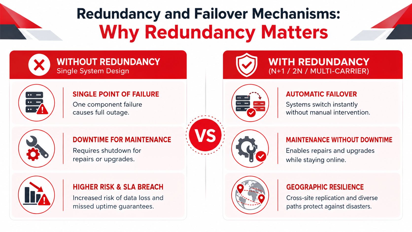
Geographic separation may be necessary for hazards that affect an entire facility or utility region. Evaluate that choice against operational complexity, replication requirements, staffing, testing effort, and total cost of ownership.
8. Physical Security Perimeter and Building Envelope
The building envelope is part of the infrastructure, not a background architectural detail. Inspect walls, doors, roof penetrations, loading areas, windows, drainage, flood exposure, ventilation openings, fencing, lighting, and camera sight lines. A damaged seal can undermine environmental control. An unobserved service entrance can undermine access control.
Use graduated zones from public approach areas to restricted operations spaces. Design clear sight lines around the perimeter, protect sensitive approaches with lighting and video coverage, and keep emergency egress routes compliant and unobstructed. Security measures must not create unsafe evacuation conditions or prevent emergency responders from reaching the facility.
Verify the condition after construction
Construction activity creates its own vulnerabilities. Review temporary doors, contractor badges, material staging, open penetrations, removed panels, roof access, and temporary network or power connections before turnover. Confirm that all permanent openings are sealed, all security devices report correctly, and all access points appear on the current site plan.
Visitor procedures should identify the host, purpose, permitted areas, escort requirements, badge return, and after-hours escalation. Coordinate recommendations with local law enforcement when the site's location, threat profile, or criticality warrants it.
Include building-envelope inspections, camera locations, access points, drainage features, and restricted areas in the as-built package. Maintenance teams need to know which seal, door, roof curb, barrier, or camera protects each boundary, and who owns its inspection.
9. Maintenance Access and Serviceability Design
A system that can't be maintained safely will eventually be bypassed, deferred, or damaged during service. Provide clear maintenance corridors, equipment pull space, lifting routes, isolation points, lighting, work surfaces, spare-parts storage, and safe access to filters, batteries, valves, panels, patch fields, and controls. Review the route from delivery dock to final equipment position before the equipment arrives.
Place frequently serviced components where technicians can reach them without entering energized or restricted areas unnecessarily. Keep cable pathways accessible, separate maintenance traffic from live services where practical, and label isolation points so a technician doesn't have to infer the correct device from a crowded room.
Make service procedures field-usable
Operational manuals should identify equipment models, manufacturer procedures, inspection intervals, safety controls, required tools, spare parts, and escalation contacts. A video or annotated photo can help with complex procedures, but it must match the installed configuration. Generic vendor documentation isn't a substitute for a project-specific record.
Schedule a walkdown with facilities, network, safety, and maintenance personnel. Have technicians locate a component, isolate it, access it, replace or inspect it, restore service, and update the work record. That exercise often reveals blocked panels, missing ladders, short patch leads, unclear labels, or doors that can't open fully.
Thermal imaging and power analysis can support routine maintenance, but the baseline must be documented first. Keep tools, spares, test equipment, and calibrated instruments available where response teams can reach them quickly.
10. Compliance, Standards, and Certification Requirements
Compliance starts during concept design, not at the final audit. Identify the standards, permits, codes, customer controls, environmental obligations, safety requirements, and certification objectives that apply to the facility. Assign each requirement to a design package, installation record, inspection, test, or operating procedure.
ANSI/TIA-942 is widely used as a foundation for data center infrastructure requirements because it addresses site location, architecture, electrical and mechanical systems, fire safety, telecommunications, security, and other physical infrastructure for facilities of any size. The standard's structure helps teams turn broad checklist expectations into buildable requirements across the facility stack. TIA's ANSI/TIA-942 overview also identifies the evolution toward TIA-942-C, with changes affecting telecommunications, power, cooling, architecture, fire protection, safety, and physical security.
Build the evidence register
Create a compliance matrix that names the requirement, responsible party, design reference, inspection method, test record, exception status, and final document location. Include certificates, commissioning results, training records, permits, inspection reports, calibration records, and approved deviations. Store the current revision where operations and auditors can access it.
Southern Tier Resources can contribute to fit-out coordination, fiber testing, structured-cabling records, and field documentation that supports the broader acceptance package. The partner's role should be explicit, with clear boundaries between construction evidence, facility certification, network certification, and owner acceptance.
Keep certification maintenance in the operating plan. Surveillance audits, design changes, equipment replacements, and altered operating procedures can affect compliance after the opening date. Teams can also review this data center predictive analysis guide when connecting operational data to maintenance and risk planning.
10-Point Data Center Infrastructure Requirements Comparison
| Component | 🔄 Implementation Complexity | ⚡ Resource & Operational Requirements | ⭐ Expected Outcomes | 📊 Ideal Use Cases | 💡 Key Advantages |
|---|---|---|---|---|---|
| Power Distribution and UPS Systems | High, complex design, ATS & redundancy integration | High CAPEX, floor/space, fuel logistics, ongoing maintenance | ⭐⭐⭐⭐ Continuous uptime; voltage regulation; protects equipment | Mission-critical data centers, hyperscalers, high-SLA services | Eliminates single points of failure; supports maintenance without downtime |
| Cooling and Environmental Control Systems | High, thermal modeling, containment, HVAC integration | Continuous energy draw, skilled HVAC ops, periodic servicing | ⭐⭐⭐⭐ Stable temps/RH; extends hardware life; enables density | High-density racks, sustainability-focused sites, hyperscale deployments | Improves PUE; enables higher density; reduces failure rates |
| Structured Cabling & Network Connectivity | Medium–High, detailed design, carrier coordination | Skilled installers, testing/certification tools, carrier contracts | ⭐⭐⭐⭐ Scalable, low-latency connectivity; simplifies troubleshooting | Multi-carrier facilities, IX/peering sites, latency-sensitive services | Standardization eases upgrades; reduces downtime; enhances resilience |
| Fire Detection & Suppression Systems | Medium, zoning, BMS integration, agent selection | Specialized suppression agents, inspections, staff training | ⭐⭐⭐ Early detection; limits damage; regulatory compliance | All data centers, high-value equipment rooms, regulated industries | Protects assets; minimizes interruption; can lower insurance costs |
| Network Security & Access Control | High, multi-layer integration, continuous tuning | Security staff, SOC tooling, ongoing operational costs | ⭐⭐⭐⭐ Prevents unauthorized access; supports compliance | Regulated data, multi-tenant sites, cloud providers | Real-time threat detection; audit trails; scalable zoning |
| Monitoring & Management Systems (DCIM) | Medium, system integrations, data calibration | DCIM software, IoT sensors, storage, analyst training | ⭐⭐⭐⭐ Proactive detection; optimized capacity and energy use | Multi-site operations, capacity planning, energy optimization | Centralized visibility; faster MTTR; data-driven decisions |
| Redundancy & Failover Mechanisms | High, architectural design, cross-site coordination | Duplicate systems, higher TCO, regular failover testing | ⭐⭐⭐⭐ Continuous operation; automated failover; DR support | SLA-critical services, cloud regions, disaster recovery plans | Eliminates single points of failure; enables maintenance w/o outage |
| Physical Security Perimeter & Building Envelope | Medium, construction & access control integration | Construction cost, barriers, guards, ongoing upkeep | ⭐⭐⭐ Deters intrusion; protects physical assets and environment | Facilities in higher-risk locations; multi-tenant campuses | Controls ingress/egress; supports safety and compliance |
| Maintenance Access & Serviceability Design | Medium, planning for access, modular layouts | Space allocation, spare parts inventory, technician training | ⭐⭐⭐ Faster repairs; reduced MTTR; safer maintenance ops | High-uptime centers, frequent refresh cycles, operator-heavy sites | Easier servicing, less disruption, better technician safety |
| Compliance, Standards & Certification Requirements | Medium–High, documentation, audits, remediation | Certification fees, compliance staff, audit cycles | ⭐⭐⭐ Ensures legal/regulatory compliance; customer trust | Regulated industries, enterprise customers, vendors requiring certs | Third-party validation; enhances marketability and trust |
Turn the Checklist Into Acceptance Evidence
A checklist becomes useful when every line item has a person who owns it and a record that proves completion. The owner may be a facilities engineer, electrical contractor, network lead, security manager, commissioning agent, or operations supervisor. Name that person before work starts, then define what “ready” means in observable terms.
For power, the acceptance package should include approved one-line diagrams, circuit schedules, UPS and generator test records, transfer results, alarm verification, battery information, grounding documentation, and maintenance procedures. For cooling, retain control sequences, sensor maps, thermal test results, failure-response records, leak detection tests, and the final equipment schedule. The drawings must show what was installed, not what the design team intended to install.
Connectivity requires its own evidence chain. Keep cable identifiers, pathway drawings, splice records, polarity checks, insertion-loss results, OTDR traces where applicable, copper certification, patching schedules, carrier demarcation records, and photographs of concealed work. A fiber link that passed testing but can't be found later is an operational liability. Southern Tier Resources can support the fiber, structured cabling, testing, and as-built documentation needed to close that gap.
Fire and security systems need witnessed verification. Confirm detection zones, alarm paths, suppression logic, release controls, access events, camera coverage, badge behavior, emergency overrides, and incident escalation. Monitoring baselines should show that facility, environmental, network, and security telemetry reaches the correct dashboards and produces the expected notifications.
Failover testing deserves special attention because diagrams and component tests don't prove system behavior. Execute the runbooks, record the starting conditions, capture alarms and operator actions, measure service behavior qualitatively, and document restoration. If the test exposes a shared dependency or an unclear decision point, correct the design or procedure before declaring readiness.
Make the handoff cross-functional
Hold a final review with facilities, network, security, safety, maintenance, construction, commissioning, and owner representatives. Walk the rooms together. Open panels, trace pathways, review labels, test access, find isolation points, inspect service clearances, and verify that the document revision on the shared system matches the field condition.
The handoff should include:
- Acceptance records: Signed test results, commissioning reports, inspection certificates, exceptions, and approved closeout actions.
- Operational procedures: Start, stop, transfer, alarm response, impairment, emergency, maintenance, and recovery runbooks.
- As-built references: Current floor plans, one-lines, control diagrams, network topology, cable schedules, equipment lists, zone maps, and photographs.
- Maintenance ownership: Frequencies, vendors, parts, tools, training requirements, warranty contacts, and escalation paths.
- Capacity evidence: Available power, cooling, pathway, panel, cabinet, and monitoring capacity, with assumptions clearly stated.
Don't mark the facility ready because every item is installed. Mark it ready when the responsible operators can locate it, test it, maintain it, recover it, and explain it using the records they received. That standard prevents the common gap between construction completion and operational readiness.
Southern Tier Resources is relevant when a project needs one coordinated partner across fiber deployment, structured cabling, fit-out execution, testing, documentation, and ongoing infrastructure response. A practical next step is to schedule the cross-functional walkdown before final acceptance, then use the findings to close installation, testing, and as-built gaps.
Southern Tier Resources provides data center fit-out support, fiber-optic installation, structured cabling, splicing, testing, documentation, and maintenance coordination for enterprise and hyperscale facilities. Visit Southern Tier Resources to discuss the infrastructure requirements, acceptance evidence, and operational handoff your next project needs.