A newly built fiber hut can look flawless: clean racks, labeled patch panels, fresh cable, and a ground rod installed outside the shelter. Then a technician opens an enclosure during troubleshooting and finds voltage where there should be none. The installation looks complete, but the fault path is open, loose, or terminated on the wrong bus.
That's the field reality of equipment grounding. Safety depends less on visible hardware than on whether fault current has a permanent, low-impedance route that can keep exposed metal near earth potential and operate the protective device. This guide focuses on the work that decides whether a retrofit is genuinely safe: mapping metallic infrastructure, verifying continuity, testing connections, and preserving evidence in the closeout package.
The Invisible Risk in Telecom Infrastructure
A ground rod in the corner proves that an electrode exists. It doesn't prove that a rack, raceway, cabinet, power distribution unit, or cable pathway is bonded into an effective fault-clearing system.
Consider a technician tracing a power issue in a recently completed fiber hut. The cabinet doors are installed, the rack grounding jumper appears to be present, and the feeder passed a visual inspection. A fault develops inside a power supply, energizing the enclosure. Because the equipment-grounding conductor is loose or improperly terminated, the return path has too much impedance. The breaker can remain energized while fault voltage sits on the metalwork.
Equipment grounding creates a low-impedance path for fault current, helps keep exposed conductive parts near earth potential, and enables protective devices to disconnect power. Improper equipment grounding has been identified as one of the most frequently cited electrical-safety violations in the United States, as summarized by the electrical safety violations reference.

Why visual completion is unreliable
A green conductor can be present and still fail in service. Common causes include a lug installed over paint, a loose connection at a rack ground bar, a missing bonding jumper across a pathway section, or a conductor landed on an isolated bus that isn't connected to the intended fault-return path.
The same inspection discipline used by certified emergency lighting contractors applies here: installation quality must be confirmed through inspection, testing, and records, not inferred from appearance. In a telecom retrofit, that means checking the entire conductive route from the equipment enclosure back to the source and documenting every correction.
Practical rule: A visible ground connection is an installation detail. A verified, continuous fault path is a safety control.
The distinction matters in data-center racks, wireless infrastructure, metallic cable trays, generators, and temporary power alike. Grounding is not a checkbox completed when the conductor is pulled. It's a design-and-verification requirement that must survive construction changes, equipment replacement, and maintenance work.
Why Grounding Is a Measurable Life-Safety Requirement
Telecom and data-center crews work around energized distribution equipment, generators, battery systems, racks, tower equipment, and temporary construction power. That environment leaves little room for assumptions about continuity or bonding.
From 2011 through 2023, 1,940 occupational deaths in the United States were classified as electrical fatalities, out of 70,692 total occupational deaths. Construction accounted for 855 of those electrical deaths. A separate NFPA summary reports an annual average of 150 workplace fatalities caused by exposure to electricity and 2,428 related injuries since 2011. These figures are reported in the electrical hazard safety summary.
Those figures don't attribute every incident to failed equipment grounding. They describe the hazardous operating environment in which grounding, bonding, de-energization, lockout/tagout, insulation, and safe work distances must function together.
Grounding is one layer, not the entire control system
An equipment-grounding conductor can help clear a fault, but it doesn't make energized work acceptable. It can't replace de-energization, verification of absence of voltage, appropriate approach boundaries, or qualified personnel.
The practical requirement is to make grounding measurable and maintainable:
- During design: Identify the source, protective device, grounding topology, equipment enclosures, metallic pathways, and bonding points.
- During installation: Inspect terminations, remove insulating coatings where required, verify compatible lugs, and protect conductors from damage.
- During commissioning: Test continuity and bonding, confirm the intended return path, and record the results against equipment and circuit identifiers.
- After modifications: Reinspect any rack, PDU, cable tray, generator, surge protector, or radio equipment affected by the work.
Teams that treat test records as part of operational documentation can identify degradation before a fault exposes it. The record should be usable by the next technician, not just filed to satisfy a closeout requirement.
Field perspective: If an owner can't identify which test proved a rack was bonded, the rack hasn't been fully accepted.
For operators planning work in occupied facilities, a practical electrical risk assessment resource can help structure the broader hazard review. Grounding should sit inside that review alongside energized work controls, access restrictions, temporary power, and maintenance procedures.
Grounding vs Bonding in Field Retrofits
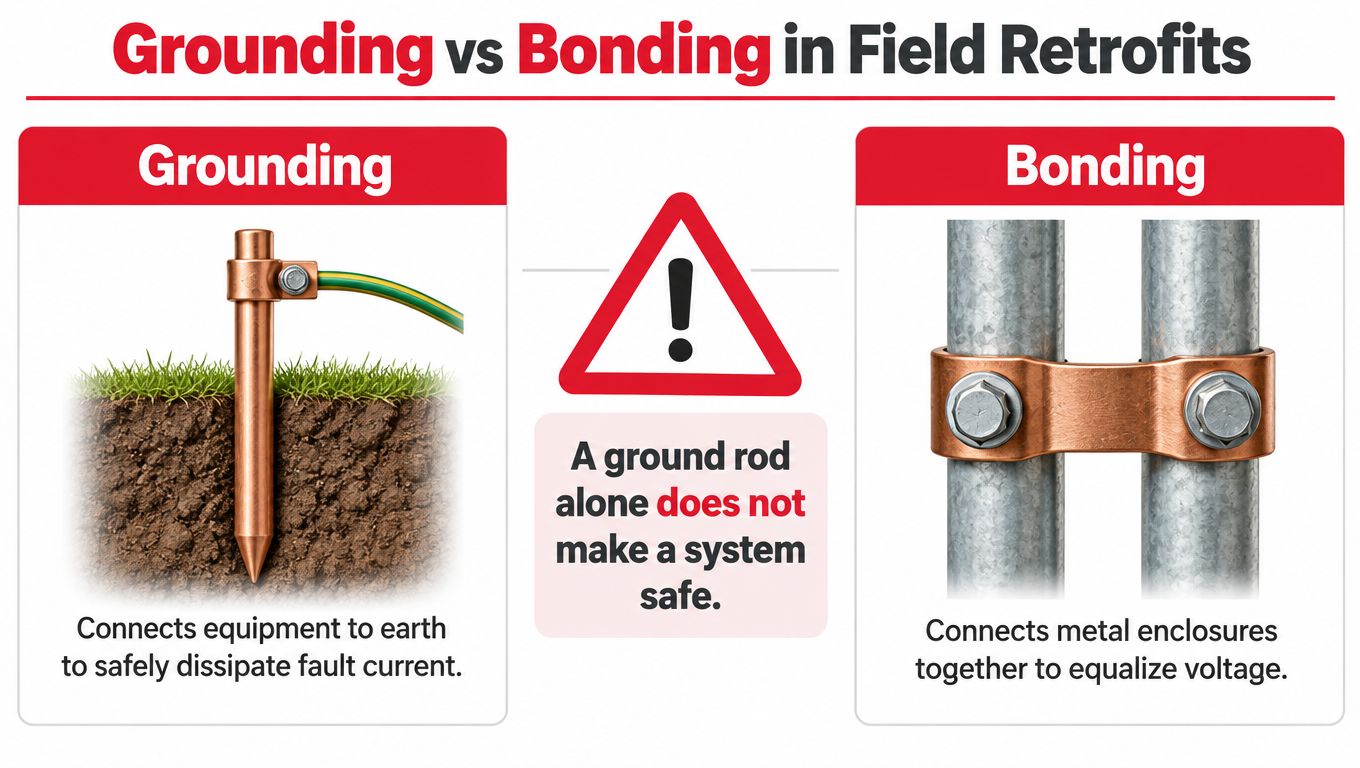
A ground rod and a bonded rack solve different problems. Grounding connects a system to earth. Bonding creates electrical continuity among conductive parts so they remain at a controlled potential and provide an effective ground-fault current path. A site can have an electrode and still have an unsafe rack, raceway, or enclosure.
NFPA makes this distinction clear in its grounding and bonding fundamentals. In a retrofit, the question isn't only whether the building or shelter reaches earth. The question is whether every conductive component that could become energized is connected into the intended fault path.
What must be mapped
Start with a physical inventory, not a one-line diagram alone. Walk the room and identify:
- Rack frames, cabinets, doors, and equipment-ground bars.
- Metallic ladder rack, tray, conduit, wireway, and support steel.
- Fiber pathway components with metallic sections or bonding hardware.
- Cable shields, surge protection devices, generators, battery cabinets, and PDUs.
- Structural steel, building steel interfaces, and legacy grounding buses.
- New equipment being added to an existing telecom or data-center system.
Mark each component on the as-built drawing or retrofit redline. A cabinet may be close to a bonded tray and still have no reliable connection to it. Paint, flexible connections, corrosion, loose lugs, and removed jumpers can break continuity without changing the appearance of the installation.
What must be tested and recorded
For each conductive path, record the point of origin, destination, conductor or bonding hardware, termination condition, test method, result, technician, and test date. Photograph connections before concealment or reassembly. If a connection is corrected, preserve the original finding and the corrective action rather than replacing the failed condition in the record.
A ground rod alone doesn't demonstrate that a rack can clear a fault.
Use the embedded demonstration as a visual supplement, but don't substitute media for field verification.
The acceptance decision should follow the fault path. Trace the equipment enclosure to the bonded equipment-ground bus and then back through the approved return route. If the path depends on a raceway, structural connection, bonding jumper, or field-installed lug, inspect that specific dependency and document it.
Sizing Equipment Grounding Conductors Correctly
For NEC-governed telecom shelters, wireless sites, and data-center fit-outs, the equipment-grounding conductor is sized primarily from the rating or setting of the upstream overcurrent protective device, not merely from the feeder conductor size. The applicable minimum copper sizes are provided in NEC Table 250.122 material published through the NFPA code-development document.
The listed minimum copper EGC sizes are:
| Upstream protective-device rating | Minimum copper EGC |
|---|---|
| 15 A | 14 AWG |
| 20 A | 12 AWG |
| 60 A | 10 AWG |
| 100 A | 8 AWG |
| 200 A | 6 AWG |
| 300 A | 4 AWG |
| 400 A | 3 AWG |
Start with the protective device
Pull the circuit schedule, inspect the upstream breaker or fuse, and confirm that the field-installed device matches the approved design. Then identify the conductor material, raceway arrangement, parallel paths, and termination hardware.
The EGC must carry enough fault current to help operate the protective device rapidly. An oversized phase conductor doesn't justify a smaller fault-return path. That combination can reduce voltage drop during normal operation while leaving the fault path inadequate during abnormal operation.
Apply proportional increases when phase conductors grow
When ungrounded conductors are increased in area for voltage drop or another design reason, the EGC generally must be increased proportionally as well. The purpose is to preserve the relationship between the phase conductors and the fault-return path.
For example, if a feeder design changes because of voltage-drop concerns, don't update only the phase conductor callout. Recalculate the EGC, revise the circuit schedule, and verify that the lugs, bonding jumpers, and equipment-ground bus can accept the selected conductor.
Verify more than conductor size
Conductor sizing is only one part of acceptance. Check that:
- Protective-device data: The installed rating or setting is documented.
- Termination capability: Lugs and bars are listed for the conductor material and size.
- Fault-duty path: Bonding jumpers and connections can carry the imposed fault current.
- Parallel installations: Each required path is installed and terminated as designed.
- As-builts: The final conductor sizes and routing match the physical installation.
A correctly sized conductor that is loose, painted over, or landed on the wrong bus still fails the field test.
Grounding Systems Across Telecom Environments
The same equipment-grounding principles behave differently depending on the site. A data-center fit-out usually offers structured buses, dense metallic pathways, and extensive rack rows. A wireless compound adds outdoor exposure, tower steel, radio equipment, generators, and long paths between equipment and the electrical source. A fiber hut may combine legacy electrical work with new racks, battery systems, and nonmetallic pathway sections.
OSHA requires grounding paths for circuits, equipment, and enclosures to be permanent and continuous. Fixed equipment must be grounded by a conductor in the same raceway, cable, or cord as the circuit conductors, and that conductor must safely carry the imposed fault current, as detailed in the OSHA electrical safety guidance.
Data-center rooms
Inspect the relationship between the equipment-ground bus, rack rows, PDUs, cable trays, ladder racks, and structural steel. Painted steel can interrupt a presumed path, while removable tray sections can lose their bonding jumpers during expansion.
The acceptance walk should follow the rack row, not stop at the nearest bus. Verify rack-to-bus continuity, tray-to-tray continuity, and the bonding of equipment that was added after the original fit-out.
Fiber huts and shelters
Shelters often contain compact equipment layouts where power, structured cabling, fiber systems, and metallic support systems share limited space. Check cabinet doors, battery enclosures, cable entry hardware, surge protection, and any metallic pathway that crosses between legacy and new work.
A new rack can inherit a poor legacy path. Treat the existing system as unverified until its continuity and terminations are inspected.
Tower compounds and temporary power
Outdoor sites add weather exposure, long conductor routes, tower interfaces, generators, and radio equipment. Temporary arrangements deserve special scrutiny because nonmetallic conduit, movable equipment, loose connections, and repeated handling can interrupt continuity.
The topology changes by environment, but the acceptance question stays consistent: can a fault reach the intended protective device through a permanent, continuous, low-impedance path?
Testing Protocols for Fixed and Portable Systems
A rack can pass a ground-resistance test while its enclosure remains isolated from the equipment-grounding path. Acceptance testing must follow the fault-current route, especially when new racks, trays, or portable power are connected to legacy infrastructure.
Fixed infrastructure
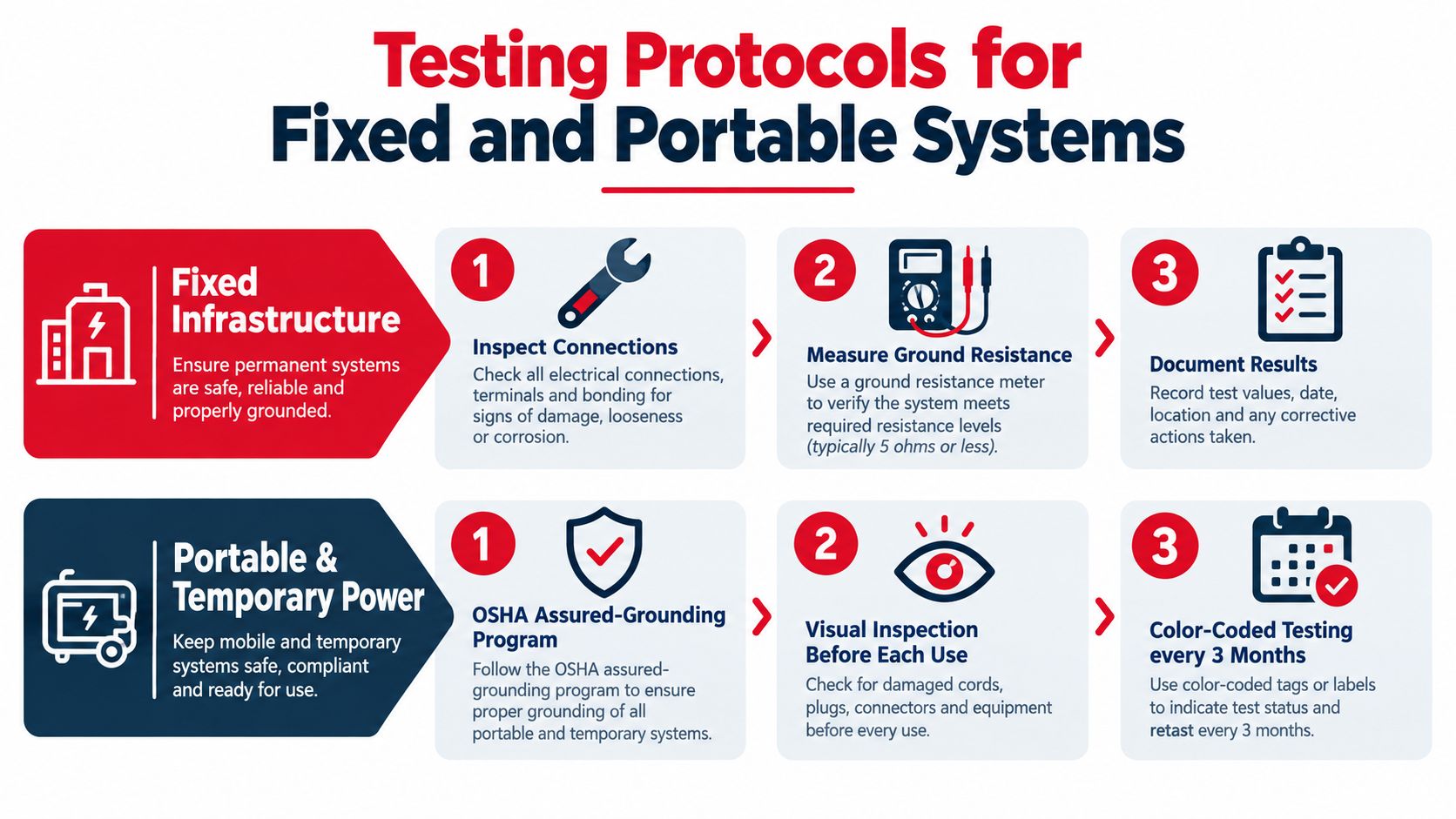
For a fixed telecom or data-center installation, assign every result to a circuit, rack, cabinet, bus, or pathway identifier. The package should include connection photographs, continuity results, test-equipment identification, marked drawings, and deficiencies corrected before acceptance.
Test the route a fault current would use, not only the grounding electrode. Electrode resistance does not prove continuity from a rack or enclosure to the bonded equipment-ground bus and protective device. Inspect bonding jumpers, terminations, contact surfaces, and any connection altered during the fit-out.
Portable and temporary power
An assured-grounding program requires visual inspection before daily use, along with continuity and terminal-connection tests. Perform testing before first use, after repair or suspected damage, and at the applicable recurring interval. Under the stated guidance, fixed protected equipment may use a longer interval than portable equipment.
A grounding electrode resistance above 25 ohms requires a supplemental electrode at least 6 feet away under OSHA construction guidance. The OSHA electrical safety material describes the rule. That electrode check still does not prove that every cord, enclosure, or portable tool has a continuous equipment-grounding path.
Keep separate records for permanent infrastructure and portable assets. A cord set needs an identifiable inspection status and test result. A rack acceptance package should show its relationship to the room bus, pathway, feeder, and protective device.
Shortcuts usually appear during troubleshooting. A record that identifies the asset, test points, result, tester, and corrective work lets the next technician isolate a failed path without repeating the entire investigation.
Testing discipline: Test after installation, after repair or modification, and store each result with the asset record.
The Field Acceptance Workflow for Retrofits
Retrofit acceptance works best as a physical walkdown tied to the drawings. Start before new equipment is installed, while legacy conditions are still visible.
- Map every conductive component. Mark racks, cabinets, trays, raceways, cable shields, battery cabinets, generators, surge protection, structural steel, and existing buses.
- Trace the intended path. Follow each enclosure and pathway back to the bonded equipment-ground bus and source. Don't assume proximity means continuity.
- Inspect connection surfaces. Look for paint, corrosion, loose lugs, damaged threads, incompatible hardware, missing jumpers, and terminations on neutral or isolated buses.
- Test rack-to-bus and pathway continuity. Assign every result to a physical identifier that appears on the as-built drawing.
- Correct and retest. A tightened lug or added jumper is not complete until the revised condition produces an acceptable test result.
- Close the record. Store photos, test values, redlines, equipment identifiers, and responsible-party signoff in the commissioning package.
The acceptance package should make future troubleshooting faster. A technician should be able to determine what was tested, where the test points were located, what failed, and what changed without reopening the entire investigation.
A ground rod may remain part of the system, but it shouldn't be the acceptance criterion for a rack or pathway. The criterion is verified continuity through the intended fault path.
Future-Proofing Grounding for High-Density Infrastructure
Higher-density facilities are changing the power systems that telecom and data-center teams must inspect. A 2026 electrical-industry review reports that the NEC 2026 framework separates grounding and bonding requirements for systems below 1,000 volts AC or 1,500 volts DC from systems above those thresholds, with new Article 270 addressing higher-voltage grounding methods, electrodes, bonding-conductor sizing, and effective ground-fault paths, as described in the NEC 2026 data-center review.
That means a low-voltage rack checklist may not be adequate for a facility adopting higher-voltage distribution, large UPS systems, DC architectures, or new power-conversion equipment. The design team must identify the voltage class, fault-current behavior, protective-device clearing, inductive effects, switching transients, lightning exposure, and parallel metallic paths.
Keep the documentation aligned with the plant
Update the one-line diagram when the power architecture changes. Update equipment layouts when racks, PDUs, pathways, or buses move. Record bonding topology, conductor routes, termination details, test points, and protective-device information in the as-built package.
The engineering principle applies beyond U.S. code terminology. Any facility adding denser power conversion and digital infrastructure needs a grounding system that is designed for the actual fault path, verified in the field, and understandable to the maintenance team.
The practical target isn't a universal resistance number. It's a documented system in which conductive parts remain controlled, fault current has an effective route, protective devices can operate as intended, and later modifications don't compromise the protection.
Southern Tier Resources provides telecom and data-center infrastructure services that include engineering, construction, maintenance, grounding coordination, electrical integration, testing, and as-built documentation. If your retrofit involves new racks, fiber pathways, wireless equipment, or power-system changes, visit Southern Tier Resources to discuss a field-ready delivery and acceptance approach.