The cable is already on site. The pull crew is waiting, the rack layout has changed twice, and someone has discovered that the pathway is tighter than the drawings suggested. The original design still looks correct in a spreadsheet, but the first bend, splice tray, and patch-panel route are exposing assumptions nobody documented.
That's where fiber optic cable design earns its value. The glass may meet the optical specification, yet the completed plant can still suffer from damaged fibers, exhausted loss margin, difficult restoration, or a handoff that leaves the operations team guessing. Good design accounts for the cable, the route, the installers, the test equipment, and the people who'll maintain the network years after the acceptance package is signed.
Why Fiber Design Decisions Shape Network Lifespan
A carrier once approved an outdoor loose-tube cable for a route ending inside a dense equipment room. The cable met the fiber-count and environmental requirements, yet installation exposed the mistake. Technicians struggled to transition it into termination hardware, used more rack space than planned, and left service loops pressing against neighboring patch cords. The cable was suitable for its rated environment. The design was not suitable for the handoff point.
The same problem appears in data centers when a compact cable is selected without checking how installers will dress it around cabinets and splice enclosures. The pull may succeed, then attenuation rises after a tray moves or a door closes against the route. Conduit fill, bend radius, slack storage, and access for testing can turn a technically correct design into an expensive service problem.
Design for the people who install and maintain it
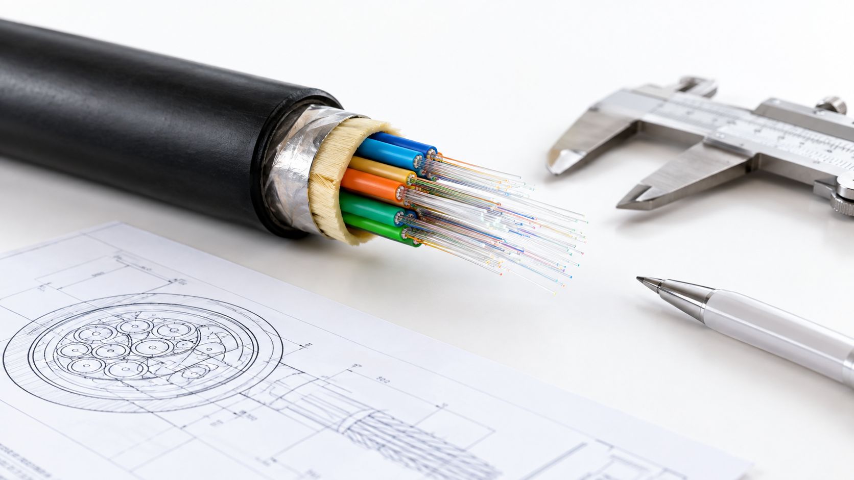
A useful design package answers more than which cable reaches the far end. It should define:
- Pathway conditions: Confirm conduit capacity, pull geometry, access points, riser transitions, tray loading, and entry hardware before procurement. A cable that fits on paper may exceed practical fill or become impossible to pull through the final bend.
- Environmental exposure: Match the jacket, water protection, armor, and strength system to the actual route, not a generic cable category.
- Termination strategy: Decide where splicing, connectorization, slack storage, and polarity management will occur. A cable that costs less on the drum can require much more labor at the panel.
- Future access: Reserve usable space for expansion, testing, and restoration. Spare fibers have limited value if technicians cannot reach the closure or manage the service loop without disturbing live patch cords.
The same checks should appear in the handoff package. Record route constraints, bend-radius requirements, splice locations, test results, and the slack locations that future technicians must protect.
Practical rule: Treat installation access and maintenance access as design inputs, not construction details.
A network lasts when its physical choices remain workable after the drawings are closed. Design the cable, pathway, rack entry, and service space as one system, then verify that installers can build it and operators can repair it.
Core Principles of Optical Transmission
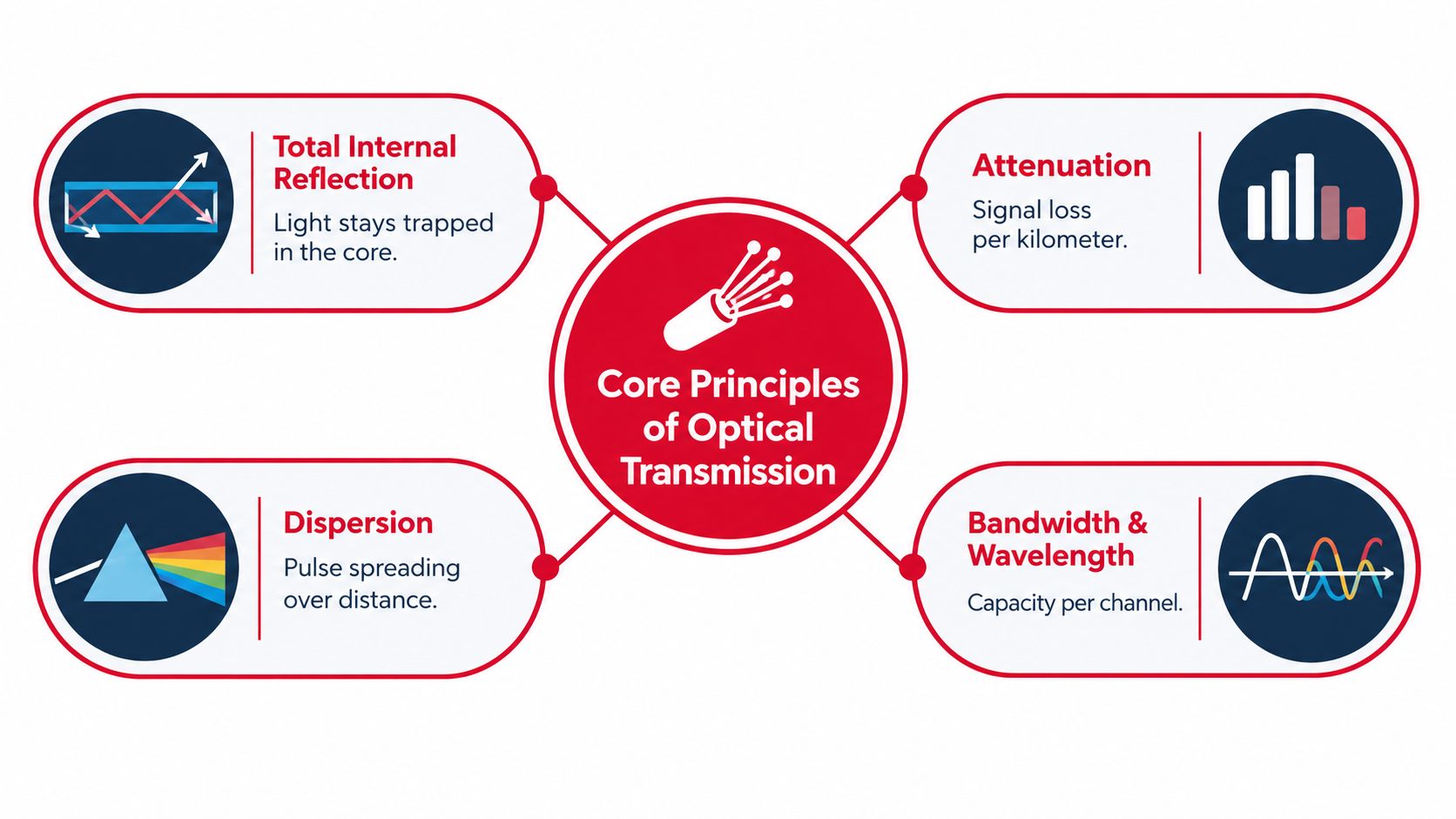
A link can pass certification and still fail in service when its optical margin was planned without the installed route in mind. Fiber design must account for attenuation, dispersion, wavelength behavior, bandwidth, and the mechanical conditions that change performance during pulling, routing, and rack handoff.
Attenuation is the loss of optical power along the link. Fiber length, splices, connectors, contaminated interfaces, and bends each consume margin. The 1966 target of below 20 dB/km and the 1970 demonstration of 17 dB/km established the low-loss foundation used in modern systems, as documented in this optical-fiber historical record. That history matters here because loss budgeting must reflect the complete installed path, not only the cable specification.
What the design must control
Total internal reflection confines light within the core when the core and cladding are correctly engineered. It cannot compensate for excessive pulling force, a crushed pathway, or a bend-radius violation introduced at a rack or closure.
Attenuation determines the power available at the receiver. Include fiber type, operating wavelength, span length, connector count, splice count, and expected bend conditions in the loss calculation. A short route with crowded panels can consume more practical margin than its drawing suggests.
Dispersion spreads pulses during transmission. As spreading increases, the receiver has more difficulty distinguishing adjacent symbols, particularly at higher speeds or longer reaches. Match the fiber and transceivers to the protocol and route length, then verify that choice during testing.
Wavelength affects attenuation, component behavior, and compatibility between the fiber and transceivers. Specify the supported operating window before procurement. Ignoring wavelength until commissioning can force optics changes after cable installation.
Field deployment turned these principles into working networks. The U.S. government connected computers at NORAD using fiber in 1975. AT&T installed an optical telephone system beneath downtown Chicago in 1977, and the first metropolitan fiber cable was deployed in Turin that year. In 1983, MCI and Corning opened a commercial 1.3-micrometer system between New York and Washington. The Corning optical communications timeline records these milestones.
Optical theory defines link capability. Installation practice determines delivered performance.
Choosing Between Loose-Tube and Tight-Buffered Cables
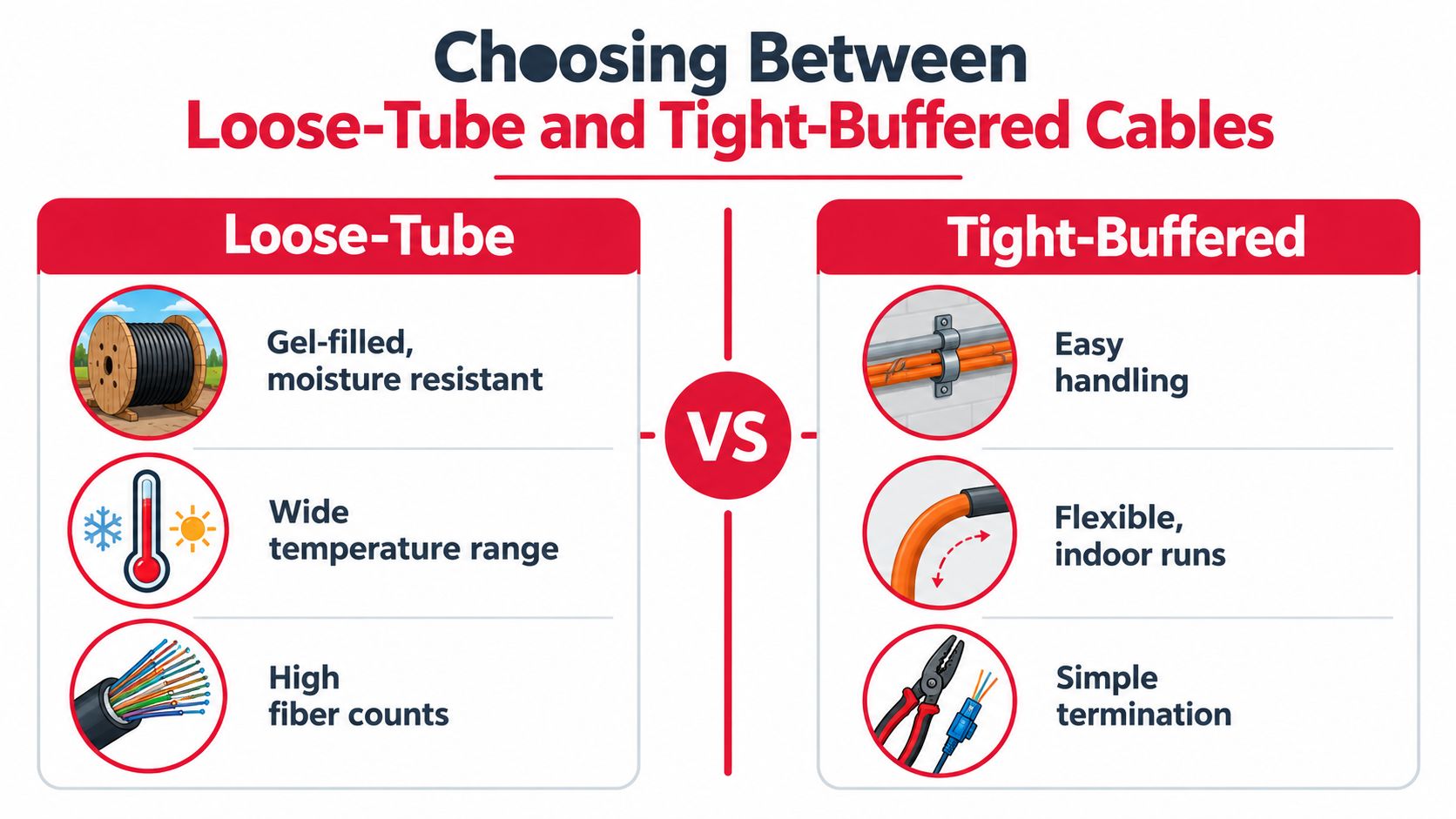
Loose-tube and tight-buffered cables solve different mechanical problems. Choosing between them by fiber count alone is how projects end up with a cable that's technically compliant but awkward to install, terminate, or repair.
Loose-tube construction places the fiber in a buffer tube with room for controlled movement. That separation helps protect the glass from cable strain, temperature changes, and outdoor handling. Loose-tube designs are a strong fit for buried, ducted, and aerial outside-plant routes where moisture protection, crush resistance, environmental exposure, and high fiber counts matter.
Tight-buffered construction surrounds each fiber with a closer protective layer. The result is generally easier handling for indoor pathways, risers, equipment rooms, and short interconnects. Technicians can route and terminate the cable without managing the same type of loose fibers and buffer tubes found in outside-plant designs.
Match the architecture to the route
| Design question | Loose-tube choice | Tight-buffered choice |
|---|---|---|
| Where is the cable installed? | Outside plant, duct, direct-burial, or aerial pathways | Indoor conduit, risers, trays, and equipment rooms |
| What threatens the fiber? | Moisture, temperature variation, crush, tension, and environmental loading | Handling, routing congestion, cabinet movement, and termination access |
| How will technicians terminate it? | Usually through splice closures, trays, and transition hardware | Often simpler for direct indoor termination and patching |
| What does restoration require? | Careful tube access and splice management | Easier individual-fiber handling, but less suited to harsh outdoor exposure |
| What happens when the route changes? | Robust cable construction may resist the environment, but can be cumbersome indoors | Flexible handling helps indoors, but the cable may lack outside-plant protection |
The transition point deserves its own drawing. A loose-tube outside cable entering a building may need a listed indoor-rated transition, a splice enclosure, or a protected pathway before it reaches the distribution frame. Conversely, a tight-buffered indoor cable should not be treated as a substitute for an outdoor cable only because it fits the conduit.
Prysmian's discussion of MDU drop cable design illustrates the same balancing act. Indoor and outdoor jackets, bend-insensitive fiber, ruggedized cable structures, microduct protection, aesthetics, and installation practices all affect the selection. The MDU cable design guidance emphasizes that a more rugged construction can improve protection while reducing flexibility or visual suitability.
Building an Accurate Loss Budget
A link can pass the spreadsheet review and still fail during commissioning. A missed patch-panel pair, an overlooked splice tray, or a bend inside a crowded rack can consume the margin that looked safe on paper. A loss budget turns product selections into an end-to-end engineering calculation. The FOA recommends evaluating distance, speed, fiber type, wavelengths, and component counts, then accounting for attenuation and bandwidth in its fiber link design guidance.
Start with the optics. Record transmitter launch power, receiver sensitivity, operating wavelength, and the manufacturer's stated optical budget. A generic transceiver distance rating is not a substitute for those limits. Optics from different generations may tolerate different loss, so a link that passes with one module can fail after a hardware refresh.
Add each loss source
Use this calculation:
Fiber attenuation + connector losses + splice losses + engineering margin = required link budget
Calculate fiber loss by multiplying the specified attenuation per kilometer by the route length. Texas Department of Transportation specifications set single-mode attenuation ceilings of 0.35 dB/km at 1310 nm and 0.25 dB/km at 1550 nm. Florida Department of Transportation specifications set 0.4 dB/km at 1310 nm and 0.3 dB/km at 1550 nm. The difference shows why both the operating wavelength and the project specification belong in the worksheet.
A 20 km span using those cited ceilings can consume roughly 5 to 8 dB before connector or splice losses are added, as calculated in the same FOA reference on fiber design. That leaves component counts, routing quality, and margin with direct consequences for acceptance.
Create separate worksheet rows for:
- Fiber attenuation: Apply the project's specified value at the operating wavelength.
- Connector insertion loss: Count every mated pair, including patch panels, test points, and intermediate frames.
- Splice loss: Include production splices and planned restoration points, including closure and tray transitions.
- Bend penalties: Allow for known routing risks at cabinet entries, dense racks, and tight panel geometry.
- Margin: Document reserve for aging, measurement uncertainty, repairs, and future changes.
Validate the installed plant
Use the budget before procurement, then test the completed link with the method required by the acceptance plan. An optical loss test set measures end-to-end insertion loss. An optical time-domain reflectometer helps locate reflective events, high-loss splices, unusual bends, and distance-to-fault conditions. Test both directions where required, and record reference settings, test wavelength, equipment calibration, and launch and receive cord details.
A failed result should trigger troubleshooting, not a reference change. Check connector cleanliness, polarity, cords, calibration, and patch-panel connections before blaming the cable. A complete acceptance package gives operations staff enough evidence to separate a design shortfall from a contaminated connector years after handoff.
Ribbon Cabling in High-Density Environments
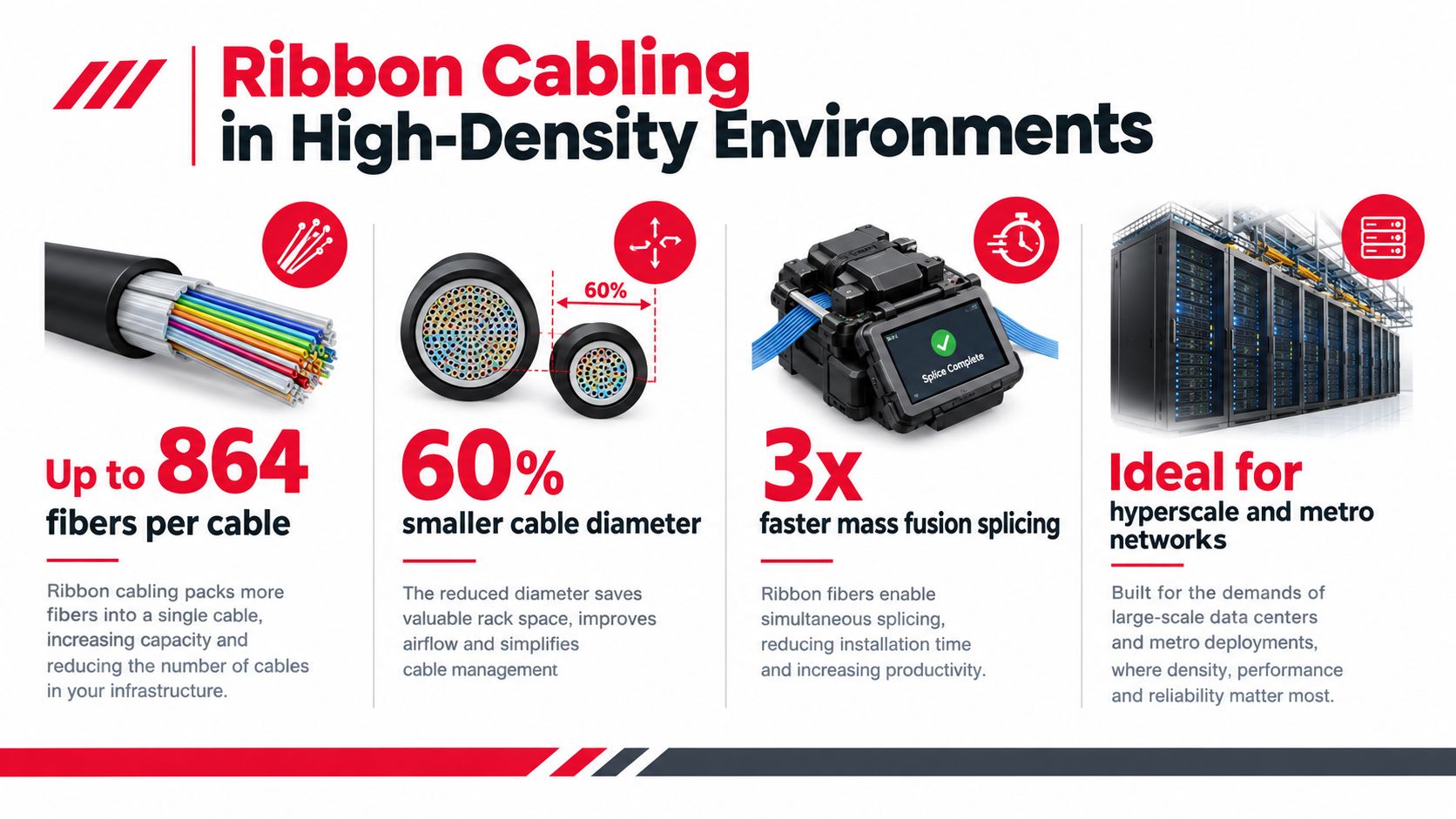
Ribbon cable can reduce the time and space associated with mass fusion splicing, but it also changes the way crews handle, organize, repair, and restore the plant. The right question isn't whether ribbon is more advanced. It's whether the operational savings justify the tighter process discipline for this route.
Independent market data forecasts ribbon designs to grow at a 10.58% CAGR through 2031, driven by hyperscale and data-center operators seeking splice-labor and conduit-fill efficiency, according to Mordor Intelligence's fiber optic cable market analysis. That same source reports that single-mode fiber represented 72.38% of market revenue in 2025, a reminder that specialized ribbon architecture is growing within a market still dominated by familiar long-reach single-mode deployments.
Where ribbon earns its place
Ribbon is compelling when the project has high fiber counts, repetitive splice work, controlled facilities, trained crews, and a strong need to maximize pathway capacity. Hyperscale campuses and dense metro aggregation sites can benefit because the architecture organizes fibers into ribbons and supports mass fusion workflows.
The trade-off appears during restoration. A damaged ribbon may affect a grouped set of fibers, and technicians need the right breakout components, splice equipment, trays, and procedures. If the local crew is trained only on individual-fiber splicing, the theoretical labor advantage can disappear during an outage.
Loose-tube cable remains preferable when routes face varied field conditions, irregular branching, frequent access changes, or crews that need maximum flexibility in handling individual fibers. Ribbon also demands disciplined stripping, ribbon identification, splice protection, and slack management. A design that saves space in the conduit can create congestion at the closure if the splice tray stack and bend paths aren't planned together.
Decision test: Choose ribbon when repeated high-count splicing and pathway efficiency are measurable project requirements. Don't choose it merely because the cable supports more fibers in less space.
Before approving the architecture, ask who will splice it, who will restore it at night, which closures support the format, and whether the warehouse carries the necessary consumables. The answer should include labor, restoration time, training, spare parts, and documentation, not just drum price.
Routing Strategies and Bend Radius Management
Most fiber failures that appear after installation aren't caused by a dramatic event. They come from a cable routed too tightly behind a panel, a service loop pulled under a tray, or a cabinet change that compresses a previously acceptable bend.
Macrobending creates non-linear insertion loss as bend radius decreases. Corning notes that many traditional all-glass communication fibers were historically unaffected above about 30 mm radius, while bend-insensitive ITU-T G.657 fibers are designed for tighter routing. Class A1 specifies a minimum bend radius of 10 mm with up to 0.75 dB added loss at 1550 nm for one turn, and Class A2 specifies 7.5 mm with up to 0.5 dB at 1550 nm for one turn, according to Corning's bend-insensitive fiber engineering note.
Keep the route buildable
Use the manufacturer's installation and storage bend-radius values, not just the minimum operating radius. Pulling, laying, coiling, and securing the cable can impose different mechanical conditions. A cable that tolerates a tight stationary bend may still be damaged if the crew exceeds its pulling tension or forces a small radius while paying it off the drum.
Plan routing in this order:
- Reserve pathway capacity: Check conduit fill, innerduct arrangement, tray occupancy, and pulling access. A route that barely accepts today's cable leaves no practical room for expansion or recovery.
- Control entry geometry: Use bell mouths, radius guides, and properly sized glands at cabinets, vaults, and closures.
- Separate fiber from pressure points: Keep cables away from sharp tray edges, door hinges, latches, and clamp locations that can crush the jacket.
- Manage slack deliberately: Store service loops in a defined radius and location. Don't coil excess cable wherever space happens to remain.
- Verify after dressing: Test links after patch-panel installation and final cable management, not only immediately after pulling.
Bend-insensitive fiber can reduce risk in dense racks, risers, and tight conduit pathways, and may improve patch-panel density. It isn't permission to ignore routing rules. The better approach combines an appropriate G.657 class with hardware, trays, closures, and installation practices that keep the cable within its mechanical limits.
Testing, Documentation, and Operational Handoff
A completed cable pull isn't a completed network. The handoff should include bidirectional test results where required, OTDR traces, insertion-loss records, connector and splice identifiers, cable routes, closure locations, rack elevations, fiber assignments, and clearly marked exceptions.
Technicians should compare the test package against the approved loss budget and as-built route. If the installed path differs from the design, update the records before acceptance. An operations team needs to know what exists, where it runs, how it was tested, and which fibers remain available.
Southern Tier Resources provides engineering, construction, fiber splicing, testing, documentation, and maintenance for telecom and data-center infrastructure. If your project needs a field-ready design and a controlled handoff, visit Southern Tier Resources to discuss the route, installation, and acceptance requirements with its team.
Review the cable architecture, route geometry, loss budget, and handoff checklist before the next drum is released. A practical fiber optic cable design should make installation straightforward, testing defensible, and future maintenance predictable.