At 11 p.m., a splice crew can finish a high-count backbone, pack the closure tools, and still face the question that determines whether the project is accepted: will the test package withstand the carrier's morning review? An OTDR trace alone rarely answers that question. Reviewers want to know how the reference was established, whether connector endfaces were inspected, which wavelengths were used, and whether the reported loss matches the engineered budget.
That gap causes many acceptance problems. The glass may be installed correctly, yet the records don't prove it because a technician skipped inspection, reused a contaminated reference cord, or relied on a single measurement that couldn't expose reflective events. Fiber optic testing standards turn a physical installation into defensible evidence by defining the method, reference condition, measurement, and acceptance decision.
Why Acceptance Testing Trips Up Even Experienced Crews
Experienced crews usually don't fail because they can't operate an optical time-domain reflectometer. They fail because the test process changes under schedule pressure. A technician may connect a familiar launch lead, select a default wavelength, capture a trace, and move on before anyone records the reference condition. That result can look professional while remaining difficult for an auditor or carrier engineer to reproduce.
The first shortcut is treating one test as complete. Insertion loss testing measures the total attenuation from end to end, but it doesn't identify where the loss occurred. An OTDR trace adds event location and event-level detail, while optical return loss or reflectance testing addresses reflections that a basic continuity check won't reveal. IEC 61280-4-2 is directly relevant to installed single-mode plant because it addresses attenuation and optical return loss, separating link qualification from component-level diagnosis through different measurements (IEC 61280-4-2).
The second shortcut is ignoring the connector sequence. A dirty endface can contaminate an adapter or reference cord, and a contaminated launch cord can create apparent loss that follows the equipment rather than the installed link. The right sequence is simple, but it has to be enforced:
- Inspect first: Examine every connector endface before mating it.
- Clean deliberately: Use the approved cleaning method for the connector and test equipment.
- Inspect again: Confirm the endface is acceptable before connection.
- Reference once, document completely: Record the cords, ports, method, and instrument settings.
Practical rule: A test result without its reference method is a number without a chain of custody.
A third shortcut is assuming that a pass at one wavelength proves the whole link. Fiber behavior changes with wavelength, and multimode acceptance requires attention to the wavelengths specified by the project and application. Similarly, an OTDR can miss or understate events when the pulse width, range, averaging, or dead-zone behavior isn't appropriate for the link.
The field decision is therefore not “OTDR or no OTDR.” It's whether the crew has produced a repeatable test record that ties clean connectors, a validated reference, complete measurements, and the as-built loss budget to the exact fiber under review. That's what turns acceptance day from a debate into a documented engineering decision.
The Standards Landscape and How TIA, IEC, ITU, and IEEE Fit Together
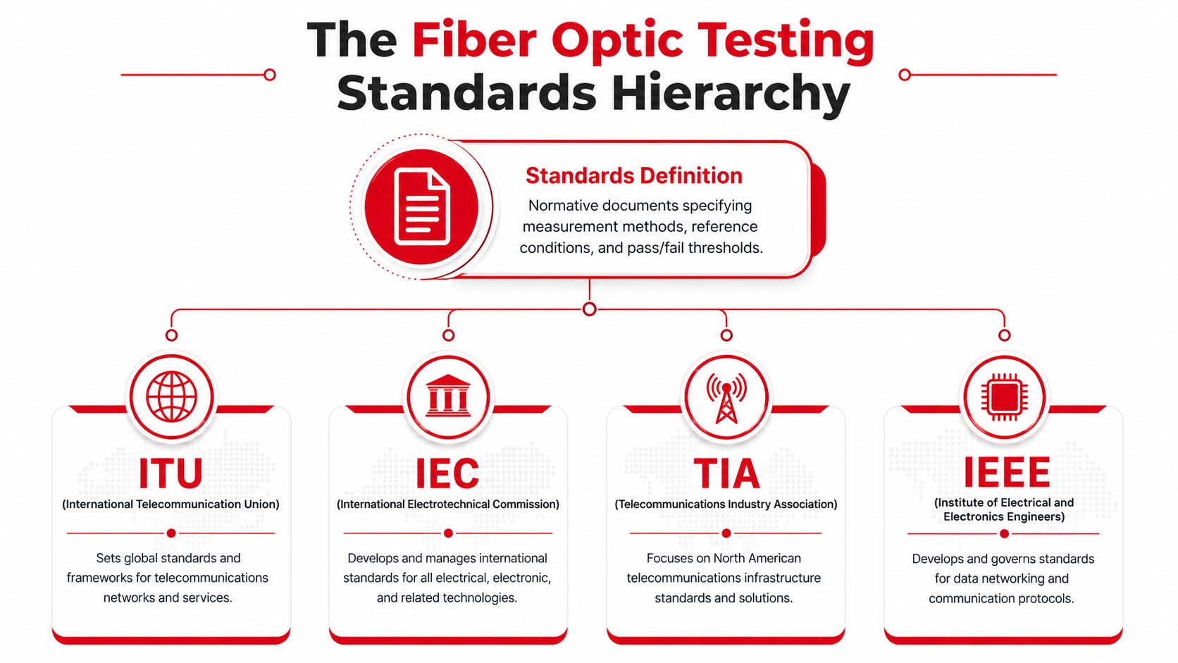
A fiber optic testing standard isn't merely a recommended instrument setting. It's a normative document that defines what to measure, how to establish the reference, what conditions apply, and how a result is judged. Without those elements, two competent technicians can test the same link and produce numbers that aren't directly comparable.
The easiest way to understand the standards is to assign each organization a practical role.
TIA defines the North American installation framework
The Telecommunications Industry Association develops cabling standards widely used for North American premises, enterprise, and data center projects. ANSI/TIA-568.3-E, published in September 2022, is the Optical Fiber Cabling and Components Standard and added references to A1-OM5, A1-OM4, and A1-OM3 designations to align with IEC 60793-2 (TIA's update on ANSI/TIA-568.3-E).
For a field team, TIA documents commonly establish the installation and certification context. They help define the link being tested, the expected reporting structure, and the relationship between cabling components and the completed channel.
IEC defines international measurement methods
The International Electrotechnical Commission supplies globally used test procedures for installed fiber, components, and environmental performance. IEC 61280-4-2 addresses installed single-mode attenuation and optical return loss. Other IEC procedures address component-level characteristics, inspection, and mechanical or environmental testing.
That distinction matters. A TIA project requirement may tell the contractor what certification evidence the owner expects, while an IEC method can define how the instrument establishes and performs the measurement.
ITU and IEEE describe the operating context
ITU-T recommendations establish international telecommunications frameworks and optical-fiber characteristics used in carrier networks. They matter when operators must engineer links that work across network boundaries and transmission systems.
IEEE standards operate at the application and network level. Ethernet specifications define the optical interfaces and link budgets that a data center or enterprise channel must support. They don't replace the physical-layer test method, but they explain why the measured loss, polarity, reflectance, and fiber category matter to the service.
Use the documents as a stack
In practice, crews should read the documents from the project outward:
- Contract and owner specification: Identify the required deliverables and acceptance limits.
- TIA or ISO/IEC cabling standard: Define the link model and certification expectations.
- IEC measurement procedure: Establish the test method and reference arrangement.
- ITU or IEEE application requirement: Confirm that the physical result supports the intended transmission system.
- As-built design: Reconcile the result with actual length, connectors, splices, and engineered margin.
The standards aren't competing rulebooks. They interlock. TIA usually frames the cabling practice, IEC supplies repeatable measurement methods, ITU supports carrier interoperability, and IEEE connects the physical result to the network application.
Core Test Methods Every Fiber Job Relies On
A defensible acceptance package uses complementary measurements because each method sees a different part of the link. Optical loss testing answers whether enough light arrives. OTDR analysis helps show where loss or reflection occurs. Return loss and reflectance testing identify energy that comes back toward the transmitter and can disturb sensitive optics.
Insertion loss measures the completed path
A light source and power meter establish a known reference and measure the end-to-end attenuation of the installed link. This is the fastest way to compare the completed channel with its allowable loss budget. It includes fiber attenuation, splice loss, connector loss, and other losses in the measured path.
The limitation is location. If the result is high, the power meter won't tell the technician whether the cause is a contaminated connector, a poor splice, a sharp bend, or excessive fiber length. That's why insertion loss is a certification foundation, not a complete diagnostic record.
OTDR analysis exposes events along the fiber
An OTDR sends optical pulses into the fiber and analyzes backscatter and reflections returning to the instrument. The trace can show the approximate position of splices, connectors, bends, breaks, and reflective events. It's especially valuable on long outside-plant links, complex campuses, and repairs where the crew needs distance-based evidence.
OTDR results depend heavily on setup. Launch and receive fibers help the technician observe the first and last connector, while pulse width and averaging affect event resolution and trace stability. A trace with poor settings can hide closely spaced events or make a normal event look unacceptable.
Return loss identifies reflection problems
Optical return loss measures reflected light relative to the launched signal, while reflectance describes reflection from a specific event. A link can show acceptable continuity and still contain a connector interface that produces problematic reflection. APC and UPC interfaces, contamination, damaged endfaces, and mismatched connector types all deserve attention when the service is sensitive to backscatter.
IEC 61280-4-2 emphasizes this separation for installed single-mode plant. The practical lesson is that OTDR alone shouldn't replace end-to-end loss and reflectance-aware testing.
| Test Method | What It Measures | What It Misses | Governing Standard |
|---|---|---|---|
| Optical loss test set | End-to-end insertion loss | Fault location and individual event diagnosis | TIA and IEC installed-cabling methods |
| OTDR | Loss, reflection, and event position along the fiber | It doesn't independently certify total channel insertion loss | IEC OTDR procedures and project requirements |
| Return loss or reflectance | Reflected optical energy from a link or event | It doesn't provide a complete attenuation budget | IEC 61280-4-2 and related reflectance methods |
Connector inspection must precede every measurement. IEC 61300-3-35 provides the inspection framework, and skipping that step can contaminate the very test equipment used to diagnose the link. For broader installation context, crews can also consult this practical low voltage cabling guide, especially when coordinating fiber work with a larger structured-cabling scope.
Singlemode vs Multimode Acceptance Criteria
Acceptance day exposes the difference between singlemode and multimode work quickly. A crew that copies one test profile across both fiber types can produce a technically neat report that does not match the installed system. Singlemode links usually support longer distances, carrier service, or backbone routes, so wavelength-dependent attenuation, connector reflectance, splice quality, and the engineered span budget receive close attention. Multimode links are common in shorter enterprise and data center channels, where launch conditions, modal behavior, connector density, and the application budget shape the result.
The project specification controls the final threshold. Fiber category labels must match the category selected in the tester and recorded in the acceptance report. ANSI/TIA-568.3-E aligned OM3, OM4, and OM5 designations with IEC terminology, so a report should identify the installed category rather than rely on an unqualified “multimode” description.
Singlemode requires wavelength and reflection discipline
A singlemode test plan commonly includes 1310 nm and 1550 nm, with other wavelengths added when the engineered system or owner requires them. Testing at the longer wavelength can expose bend-related problems that remain hidden at the shorter wavelength. Carrier acceptance packages should identify connector types and reflection limits separately. Treating every interface as interchangeable can turn a reflective connection into a false pass.
IEC 61280-4-2 provides the installed-fiber reference for attenuation and optical return loss on single-mode cable plant. Use that framework when acceptance depends on both the loss budget and reflective behavior, not loss alone.
Multimode depends on launch control
Multimode measurements change with the way light enters the core. The reference setup must match the fiber under test, and the specification may require controlled launch conditions, such as an encircled-flux-compliant source or a mandrel arrangement. Test at the wavelengths specified for the application. Many multimode plans include both 850 nm and 1300 nm to characterize the channel across its operating window.
Reference choice changes the reported loss. TIA commonly uses a one-jumper reference, while ISO/IEC 14763-3 provides two-jumper and three-jumper approaches when test cords differ from the permanent link. Including or excluding a mated interface changes the measurement. State the method, cord configuration, and fiber category in the report instead of presenting an unexplained pass or fail.
| Parameter | Singlemode OS2 | Multimode OM3/OM4 |
|---|---|---|
| Typical application | Carrier, metro, long-haul, and backbone links | Enterprise, campus, and data center links |
| Primary wavelength considerations | 1310 nm and 1550 nm, with project-specific additions | 850 nm and 1300 nm where required by the test plan |
| Main field risks | Reflectance, bends, splice quality, and span attenuation | Launch condition, modal behavior, connector density, and polarity |
| Acceptance basis | Engineered attenuation and reflectance limits | Application budget, fiber category, launch condition, and reference method |
| Useful diagnostic method | Bidirectional OTDR with loss and reflection review | OLTS certification supplemented by OTDR when event detail is needed |
A generic dB-per-kilometer value is not a pass or fail by itself. Build the link model with actual fiber length, connector interfaces, splice count, test reference, and application budget. Place that calculation beside the measured result so an auditor, carrier, or commissioning team can reproduce the acceptance decision.
Step-by-Step Field Procedure for a Standards-Compliant Test
Acceptance day exposes weak test plans quickly. A crew may record a passing loss result, then discover that a dirty connector, unstable reference, or inconsistent cord setup invalidates the reading. Keep the sequence fixed so each result remains defensible after later troubleshooting.
1. Inspect, clean, and inspect again
Inspect every endface entering the test path, including launch and receive cords, adapters, patch-panel ports, and both ends of the link. Use an inspection microscope and evaluate the image against the project's adopted IEC 61300-3-35 criteria. If contamination appears, clean the endface and inspect it again.
A visual fault locator cannot replace inspection. It can help locate a break or severe bend, but it cannot certify endface cleanliness or measure installed loss. Do not connect a questionable endface to a reference cord and assume the instrument will expose the problem.
2. Establish the reference
Set the reference with known-good launch equipment matched to the fiber type and connector interface. Write the selected method into the test plan before the crew begins. TIA commonly uses a one-jumper reference, while ISO/IEC 14763-3 defines two-jumper and three-jumper approaches when the test cords differ from the permanent link.
Record the instrument and cord identifiers, connector type, reference method, wavelength, and date. If the reference drifts or fails to stabilize, stop testing and correct it first. A reference reset after partial testing can make earlier results difficult to defend.
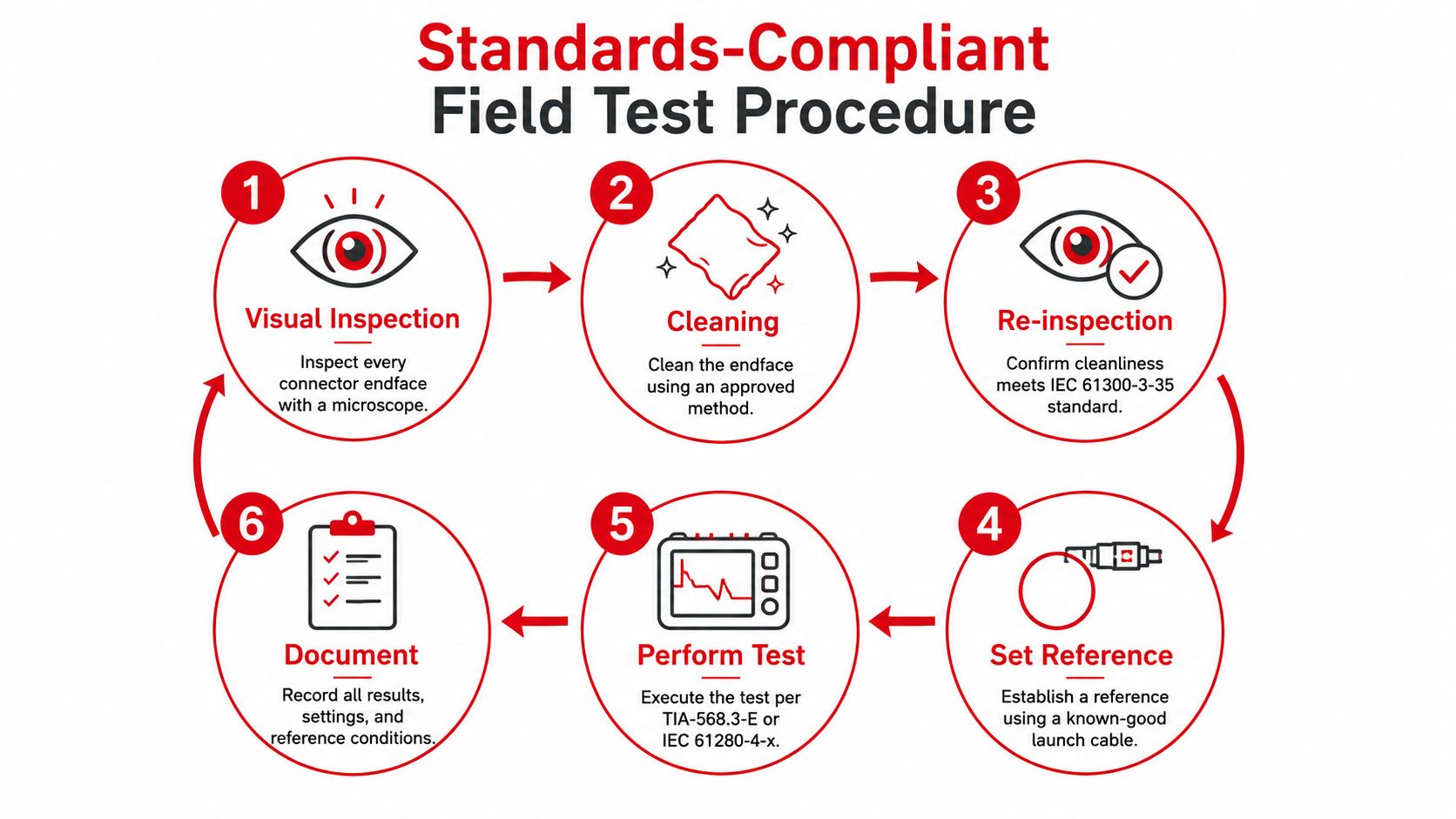
3. Measure insertion loss
Test every wavelength required by the contract and test plan. Test both directions where bidirectional certification is specified. Keep the launch and receive arrangement consistent, and save raw readings rather than only the instrument's pass or fail screen.
4. Capture OTDR traces
Shoot from both ends when the acceptance plan requires event-level evidence. Choose a range and pulse width suited to the span, apply appropriate averaging, and save those settings with each trace. Review the first connector, every splice, the far-end event, and any suspected bend or reflection. A trace without its settings gives the reviewer less basis for judging the result.
5. Check return loss or reflectance
Measure reflective behavior at the interfaces and wavelengths specified by the design. Give this review particular attention where connected optics are sensitive to reflection. Confirm that APC and UPC interfaces are not mixed.
6. Reconcile and document
Compare measured results with the as-built loss budget. Flag marginal fibers for a controlled retest instead of immediately re-splicing them. Inspect and clean again, verify the reference, confirm the test cord, and repeat the measurement. Dirty launch cables and mismatched references can create false failures, while an undocumented reset can create an apparent false pass.
A short field testing procedure video helps technicians visualize the sequence, but the project test plan remains the governing record.
Carrier Backbones and Data Center Builds Compared
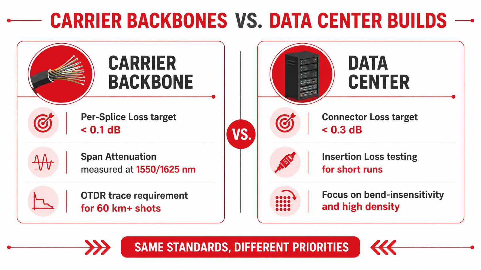
A carrier backbone and a data center spine may use the same broad family of fiber optic testing standards, but the acceptance conversation is different. The carrier engineer wants evidence that the entire engineered span behaves correctly across distance, splices, bends, and reflective events. The data center quality team wants repeatable, high-throughput certification across dense connector fields, often with MPO assemblies and short multimode links.
The carrier backbone
A long outside-plant build demands a trace that tells a complete story. The test plan commonly emphasizes bidirectional OTDR work, span attenuation at the wavelengths selected by the design, splice-event review, and reconciliation against the optical power budget. The crew must also distinguish a real event from a measurement artifact caused by launch quality, dead zones, or an incorrectly selected pulse width.
Carrier documentation should connect each trace to a fiber identifier, route segment, closure, splice plan, and test direction. A single end trace can hide the effect of a near-end event or make a far-end event difficult to interpret. Bidirectional review gives the acceptance engineer a stronger basis for judging splice loss and reflectance.
The data center build
A data center spine often contains short, high-density channels where total insertion loss, polarity, connector cleanliness, and repeatability matter more than long-span event resolution. Tier 1 optical loss testing gives the quality team a fast end-to-end result, while OTDR work becomes more valuable for troubleshooting, complex pathways, or a contract that requires event characterization.
MPO and MTP assemblies add another layer. The crew must verify polarity, connector type, keying, fiber count, and the intended migration path before measuring loss. A channel can be clean and within its loss budget yet fail to establish a link if transmit and receive positions don't align.
Choose evidence for the owner's risk
| Build type | Primary acceptance evidence | Common field risk | Useful supplement |
|---|---|---|---|
| Carrier backbone | Bidirectional OTDR, insertion loss, budget reconciliation, and reflection review | Unresolved splice, bend, or reflective event | Additional trace analysis and targeted retest |
| Data center spine | Repeatable OLTS results, polarity verification, and connector inspection | Contaminated or mismatched high-density interfaces | OTDR for diagnosis or contractual Tier 2 evidence |
The wrong approach is to apply a data center shortcut to a carrier span, or to demand long-haul diagnostic detail for every short patch-field measurement without considering the owner's acceptance criteria. Same standards, different priorities is the useful operating principle.
Compliance Checklist and Documentation That Holds Up
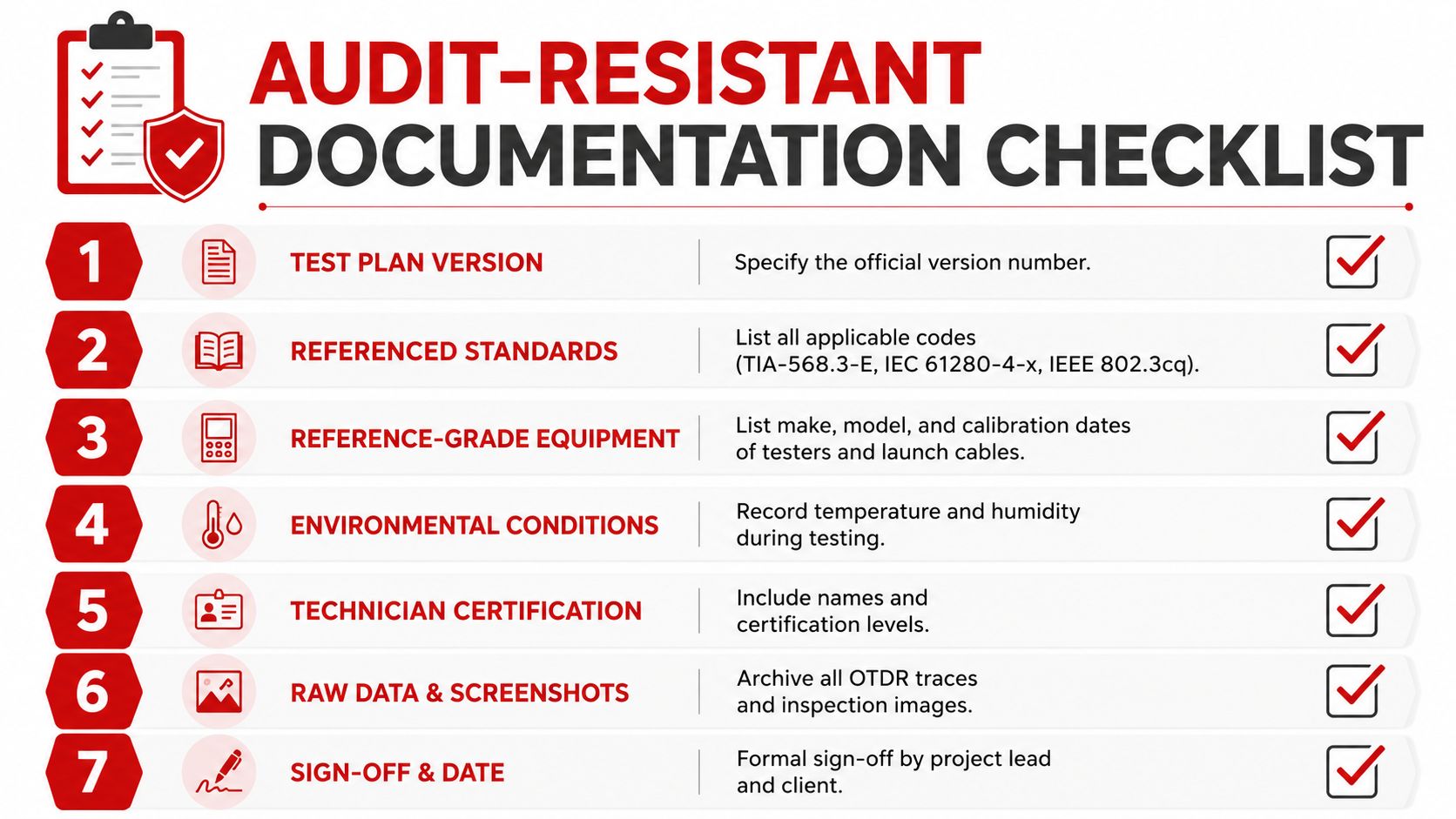
A test package becomes audit-resistant before the first connector is plugged in. The project manager, quality lead, and test supervisor should agree on the method of record, applicable standards, naming convention, and required files before crews begin production testing. If those decisions remain informal, technicians will fill the gaps with personal habits.
Define the test plan
The plan should identify the governing cabling standard, the applicable IEC measurement procedures, the fiber type, connector interfaces, wavelengths, reference method, direction of testing, and acceptance limits. It should also state how the team handles marginal results, failed inspection images, missing traces, and deviations from the engineered design.
Standards evolve. NECA/FOA 301-2016, Installing and Testing Fiber Optics, was revised in October 2016 after earlier editions in December 2004 and December 2009, reflecting the maturation of more standardized installation and acceptance procedures (NECA/FOA 301-2016 PDF). The FOA standards library also describes a longer lineage in which foundational fiber standards moved from EIA committees to TIA after organizational changes. A test plan should therefore name the exact edition, not just say “TIA compliant.”
Capture the evidence set
Use this checklist for each link or documented test group:
- Test plan version: Record the approved revision and effective date.
- Referenced standards: List every TIA, IEC, ISO/IEC, ITU, or IEEE document that governs the result.
- Equipment identity: Capture tester make, model, serial number, software version, and calibration status.
- Reference condition: Record launch and receive cord identifiers, connector types, reference method, and reference verification.
- Inspection evidence: Save pass or fail images for the relevant endfaces, not merely a technician's statement that cleaning occurred.
- Raw measurements: Archive insertion loss results, OTDR traces, wavelengths, pulse settings, range, averaging, and test direction.
- Budget reconciliation: Show fiber length, connector interfaces, splice count, allocated losses, measured loss, and remaining margin.
- Technician record: Include the technician's name, certification or authorization identifier, test date, and sign-off.
- Deviation log: Explain every accepted exception, its approval, and the disposition required for future maintenance.
Make the record useful after acceptance
The test package shouldn't exist only to secure a signature. Future maintenance crews need to identify the fiber, understand the original reference method, compare new readings with the baseline, and locate the relevant closure or patch field. Store raw files with the as-built drawings and splice documentation, and preserve the relationship between the physical fiber label and the electronic result.
Environmental qualification is also becoming more failure-specific. Recent IEC work has addressed aerial durability, including aeolian vibration for ADSS, OPGW, and OPPC cables, as well as compound flow and drip behavior for filled or flooded cables. TIA also revised a salt-spray corrosion test in September 2025, showing why outside-plant procurement and QA documents may need more than basic optical performance criteria (telecommunications standards update).
Southern Tier Resources provides fiber engineering, construction, splicing, testing, and documentation for carrier, broadband, data center, and other telecom infrastructure projects. If your next acceptance package needs field execution tied to standards-based records, visit Southern Tier Resources to discuss the test scope, as-built requirements, and project handoff with its infrastructure team.