The call always comes at the same time. A crew is on-site, the racks are open, the fiber count is higher than expected, and someone wants to know whether they should start terminating every strand in the room or switch to pre-terminated assemblies and move faster. That decision usually matters more than the hand skills, because a clean-looking termination that misses the loss budget still fails acceptance.
How to terminate fiber optic network cable starts with restraint, not tools. In carrier rooms, greenfield broadband builds, and hyperscale fit-outs, the right answer is often to avoid field termination where you can and use fusion splicing or pre-terminated assemblies where they fit the design. When the job does call for field work, the process is built around two dominant methods, connectorized terminations and fusion splicing, each with its own labor profile, rework risk, and loss target (fiber termination overview).
Why Termination Method Selection Determines Project Success
A crew can waste a full shift asking how to terminate a cable before asking whether the cable should be terminated on site at all. On a dense data center fit-out, that choice decides whether the day stays on schedule or turns into a rework loop where every dirty endface and poor cleave adds another test failure. The first pass should always be a method decision based on the loss budget, the environment, and how many strands have to be finished without creating avoidable callbacks.

What actually drives the decision
Connectorized terminations still make sense when the run is short, the strand count is low, or the job is an emergency repair and the priority is getting service back up fast. Fusion splicing fits better when a crew has many terminations to complete and the project depends on repeatable low loss. Pre-terminated assemblies remove even more on-site variability, which is why they show up so often in high-density deployments where field cleanliness and rework risk are expensive.
Practical rule: if the job can be solved with a factory-built assembly, do not force a field-polished answer just to use the cable already on site.
That approach matches how large builds are handled now. Field practice is built around repeatable preparation steps, and technicians are expected to protect the loss budget instead of improvising under pressure (industry process guide). Endface quality, cleanliness, and alignment decide whether the network passes or becomes a callback.
The practical cost of choosing wrong
Bad method selection shows up as labor waste first, then as test failure. If a crew spends hours field-installing connectors on a run that should have been prefabricated, they have traded speed for variability. If they try to force mechanical terminations into a large carrier build, they usually pay for it later in higher rework risk and more time spent on inspection and retesting.
| Criterion | Mechanical Connectors | Fusion Splicing | Pre-Terminated Assemblies |
|---|---|---|---|
| Labor profile | Fast for limited, local work | Efficient for repeated terminations | Minimal on-site termination labor |
| Loss control | Depends heavily on technique | Strong when prep and alignment are disciplined | Predictable because the factory controls the build |
| Rework risk | Higher in dirty or rushed field conditions | Lower when the prep sequence is followed | Lowest on-site, but planning matters |
| Tooling load | Lower upfront, but still needs careful prep tools | Requires a splicer, cleaver, inspection, and test gear | Requires installation discipline, not field assembly |
| Best use case | Repairs, small enterprise jobs | Carrier, ISP, and data center builds | High-density deployments and time-sensitive installs |
For a closer look at how fusion splicing is used in field and buildout work, see Southern Tier Resources' overview of fiber optic splicing.
An experienced crew makes the boring choice. Boring is good in fiber. Boring means fewer surprises, cleaner acceptance testing, and less time explaining to a client why one strand failed while the rest passed.
Choosing Between Mechanical Connectors and Fusion Splicing
A bad method choice shows up later in loss, rework, and wasted crew time. Mechanical connectors can be the right call for a restore, a short run, or a tight space where getting service back online matters more than building the cleanest possible termination path. They are also easier to justify when the job is small enough that setting up a full splice workflow would cost more time than it saves.
Mechanical connectors
Mechanical connectors work well when flexibility matters more than throughput. A technician can finish a link without bringing in a fusion splicer, which helps in limited-access rooms, emergency repairs, and small enterprise work where the job has to be closed out fast. The trade-off is consistency. A rough cleave, dust on the endface, or a poor seat can push loss beyond the practical target, and once that happens the “quick fix” turns into inspection, retest, and rework.
Fusion splicing
Fusion splicing is the better fit for carrier and data center builds because it removes a lot of the variability from the most sensitive part of the job. The fibers are stripped, cleaved, aligned, and joined by an electric arc, then protected in a splice sleeve. The loss target is tighter than with a field connector, so the prep sequence has to be disciplined. For a plain-language explanation of the process itself, see what fiber optic splicing means. That is why crews use fusion splicing when the loss budget is tight and they cannot afford to keep revisiting a strand.
Pre-terminated assemblies
Pre-terminated assemblies push the termination work back to the factory. On dense builds, that removes a lot of field contamination risk and cuts down the amount of delicate work done on site. It also avoids the common failure mode where a crew is trying to finish fine fiber work in a dusty room, under schedule pressure, while the client is waiting for the rack to light.
Factory-built assemblies are often the cleaner answer when the project is planned well and the pathway is already known. They reduce rework risk, but they demand better coordination up front, because a bad measurement or a missed route can slow the entire install.
Modern splicer workflows have also made fusion more practical on active projects, because the tool can show estimated loss at the workbench and give the crew faster feedback before they close the tray. That does not make connectors obsolete. It does mean the decision should be based on the job in front of you, not on habit or whatever kit happens to be on the truck.
Field takeaway: choose the method that gives you the lowest rework risk for the strand count and environment you are standing in, not the method that feels most familiar.
Preparing the Cable for a Clean Termination
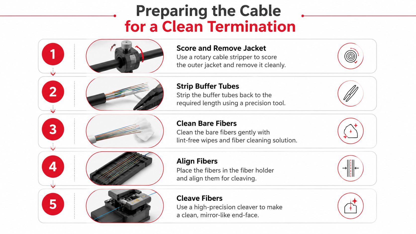
Most termination failures start before the connector or splicer ever touches the fiber. The prep stage is where the cable either becomes easy to finish or turns into a string of small problems that show up later as high loss, a failed inspection, or an OTDR trace nobody wants to explain. Good prep is repetitive, careful, and slightly boring, which is exactly why it works.
Strip in the right sequence
Current field guidance has standardized strip lengths such as 40 to 50 mm for jacket removal and 25 to 30 mm for buffer stripping before cleaving (standard prep lengths). Those numbers matter because they create enough exposed fiber to work cleanly without overhandling the strand. Shortcuts here usually lead to damaged coating, awkward tool angles, or a cleave that's harder to seat correctly.
Use the right stripper for the layer you're removing. A jacket stripper is not a buffer stripper, and either one is a poor substitute for a dedicated fiber tool. The more exact the strip, the easier the next step becomes.
Clean before you cleave, not after
Alcohol cleaning and lint-free wipes are not ceremonial steps. They remove contamination that can scratch the endface, interfere with alignment, or leave debris on the cleave surface. Practitioner guidance explicitly warns against touching the cleaved endface and emphasizes cleaning with alcohol before assembly (cleaning and handling guidance).
The cleanest fiber job is the one where nobody improvises with a sleeve of clothing, a paper towel, or a quick blow of air.
Cleave for geometry, not convenience
The cleave defines the endface geometry, and that geometry drives optical performance. A dedicated cleaver gives the flat, perpendicular cut that both connectors and fusion splicers need. Improvised cutting tools don't just look rough, they create alignment problems that show up later as measurable loss or repeat failures during inspection and test (fiber endface and cleave guidance).
If the cleave looks questionable, redo it. That's cheaper than a failed acceptance test and a callback after the crew has already been demobilized.
Executing the Termination and Splice
Once the cable is prepared correctly, the actual termination is straightforward. That doesn't mean it's casual. The insertion or splice step is where a clean prep can still be ruined by handling mistakes, dust, or rushing the final movement that seats the fiber.
Mechanical connector insertion
With connectorized work, the prepared fiber goes into the pre-assembled connector body and is secured according to the connector design. The key is to avoid side pressure and avoid touching the cleaved endface. Any contact at that stage can introduce contamination or damage the polished surface before the connector is even protected. If the connector relies on a mechanical clamp or internal alignment feature, follow the manufacturer's sequence exactly, because the design tolerances are not forgiving.
Fusion splicing in the field
Fusion work is more controlled. The fibers are placed in the splicer, aligned, and welded with an electric arc. The machine handles the alignment and shows estimated loss on-device, which speeds up decision-making in the field and helps technicians spot a weak splice before it gets closed up. Modern splicers can finish the weld in seconds, which is one reason splicing has become so practical in carrier and data center work (modern splice workflow).
After the splice, protect it with a heat-shrink or splice sleeve. That protection is not optional. It keeps the splice stable while the tray or closure is dressed and helps preserve the alignment that was just achieved.
Keeping consistency across a long shift
Wind, dust, and temperature swings all make field work harder, especially outside or in unfinished spaces. Crews stay consistent by keeping the work area controlled, staging tools before the first strand, and inspecting each termination before moving on. The crews that finish hundreds of strands successfully don't work faster by improvising. They work faster because they repeat the same clean sequence without deviation.
For technicians who want a deeper splicing walkthrough, the fiber splicing guide from Southern Tier Resources is a useful reference point for the workflow itself.
Testing and Verifying Optical Performance
A termination is not finished when the connector clicks home or the splice sleeve closes. It is finished when the link carries light inside the loss budget the job was built around. Crews that work this way avoid the costly habit of assuming a clean-looking endface equals a good circuit.
What to test and why
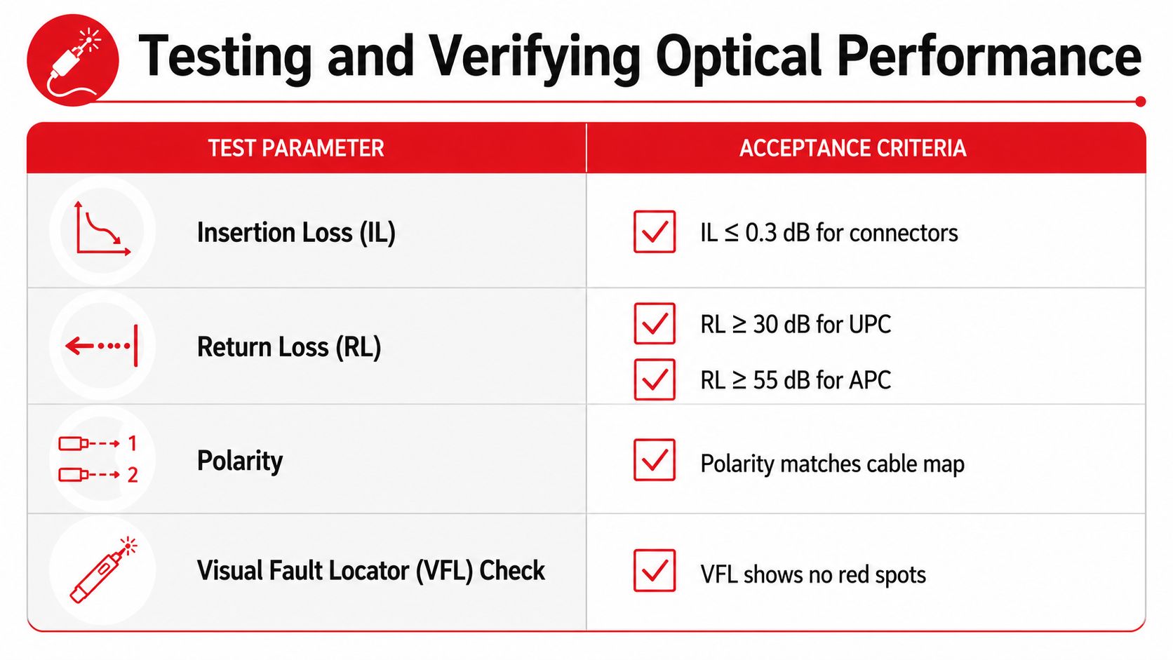
OTDR testing shows how the link behaves end to end. It exposes reflections, loss events, and distance-to-fault details that a simple visual check will miss. Optical power meter testing confirms insertion loss at the connection points, which is the number that matters when a handoff gets accepted. A visual fault locator still has a place for obvious breaks or routing mistakes, but it is a quick locator, not a pass-fail test.
Use the tester that matches the job, then compare the result to the loss budget the design allows. Practitioner guidance commonly holds connectors to less than 0.75 dB loss and splices to less than 0.3 dB loss, and it treats single-mode splice estimates above 0.1 dB as a reason to re-splice. Those are not abstract targets. They decide whether the strand gets signed off or pulled back open (loss thresholds and inspection guidance). For a field sequence that matches how crews verify links, the fiber test process from Southern Tier Resources is a useful reference.
Inspection catches problems before the trace does
A microscope inspection at 200 to 400x catches scratches, pits, haze, and dust before those defects turn into loss or reflection problems. That step saves time because it finds the bad interface at the strand level, before the closure is sealed and the paperwork says the link is good (field verification guide).
The practical rule is simple. Inspect first, test second, then act on the result. If the reading misses the target, re-terminate or re-splice instead of trying to justify the number. Fiber does not improve because the schedule is tight.
Recordkeeping matters
Keep the OTDR trace, power readings, polarity check, and pass-fail notes tied to the strand label. That record protects the installer during acceptance and gives the customer something usable when the link needs troubleshooting later. It also prevents wasted time when several fibers are open in the same tray and the crew needs to know exactly which one failed.
The best test report is the one that lets the next technician repeat the result without guessing. If a circuit passes, the trace and power level should show why. If it fails, the record should point straight to the connector, the splice, or the bend that caused the problem.
Safety Protocols and Troubleshooting Common Failures
Fiber work looks clean from a distance, but the hazards are real. You're dealing with laser light exposure, tiny glass shards, and cleaning chemicals, and none of those mistakes gets better because the crew is under schedule pressure. Good crews treat safety like part of the termination, not like a separate compliance lecture.
Laser safety starts with not looking into live fiber and not assuming a dark strand is a dead strand. Glass shard control starts with a proper disposal process for scrap ends and a clean work surface. Chemical handling means using cleaning materials as intended and keeping them away from unnecessary contact with skin and equipment.
Good troubleshooting starts with the basics, not with the OTDR. If the connector is dirty or the cleave is poor, the trace is just reporting the damage you already caused.
The failure patterns are familiar. High-loss splices usually trace back to a bad cleave, poor alignment, or contamination. Connector contamination can look like a bad device when the actual problem is the endface. OTDR ghost reflections can mislead inexperienced testers into chasing the wrong section of the link, so the technician has to separate true events from artifacts before declaring a strand bad.
When in doubt, go back to the physical interface first. Inspect the connector, clean it properly, and re-test. If the splice estimate is out of tolerance, re-splice it instead of trying to bury the issue in documentation. The technician who solves the strand at the tray saves more time than the one who keeps re-running tests on a bad termination.
Best Practices for Reliable Fiber Deployments
Reliable fiber work comes from matching the method to the deployment, not from chasing a single “best” technique. Dense carrier rooms, hyperscale data centers, broadband buildouts, and small enterprise jobs all deserve different answers. The project succeeds when the crew chooses the path that fits the loss budget, the strand count, the environment, and the schedule.
What to standardize on every job
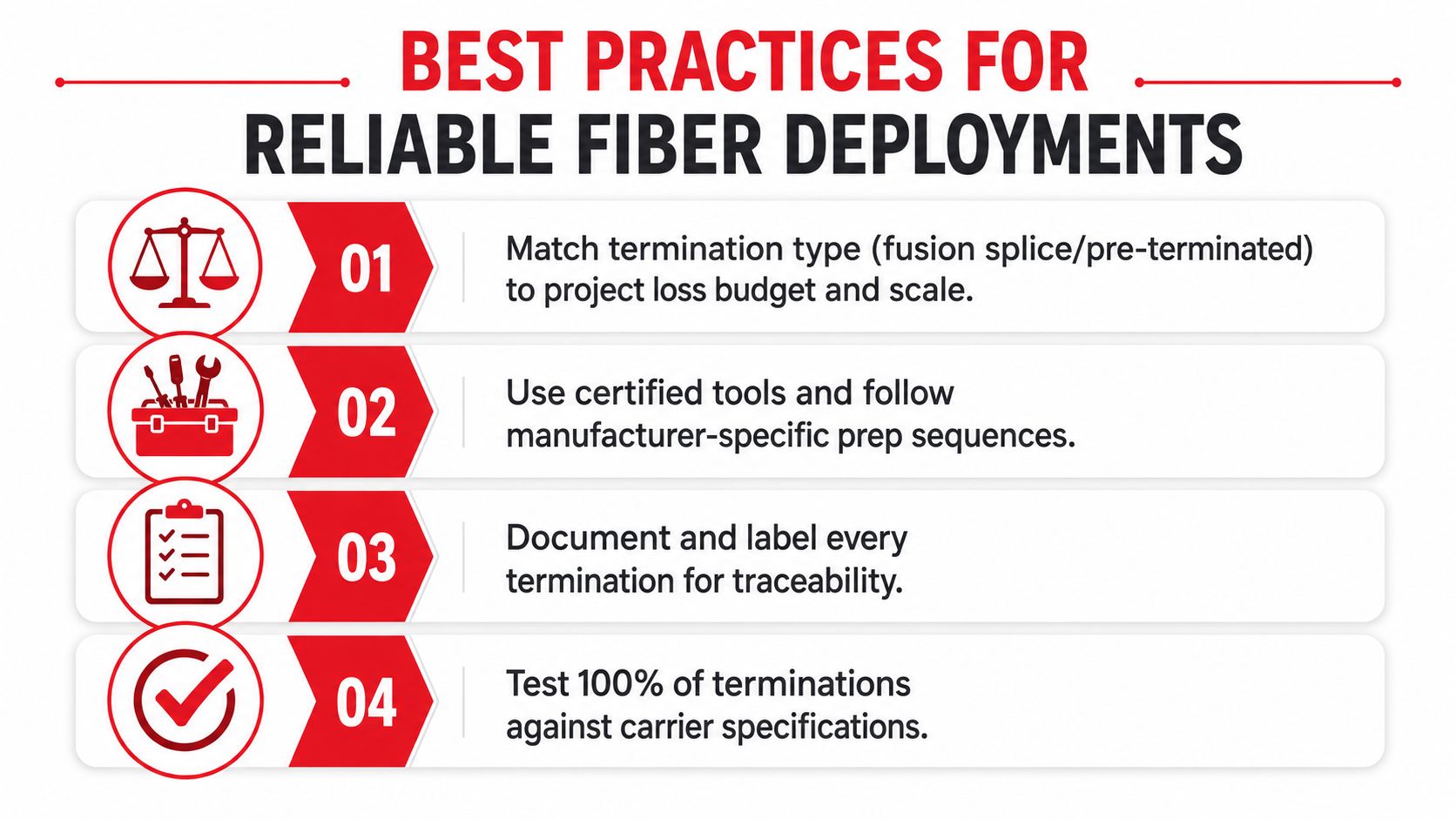
- Match the termination type to the build: Use fusion splicing or pre-terminated assemblies when the project scale and loss budget call for lower rework risk.
- Use certified tools and follow the prep sequence: Dedicated cleavers, inspection scopes, and cleaning tools do the work that improvised methods can't.
- Document every termination: Label strands, save test results, and keep trace files with the as-built package.
- Test every finished strand: Verify against the accepted loss target before you close the tray or demobilize the crew.
That framework is exactly why structured fiber contractors stay busy on high-stakes projects. Southern Tier Resources, for example, handles fiber-optic infrastructure work, including engineering, construction, testing, and documentation, which is the kind of end-to-end scope that keeps termination decisions aligned with the actual network design rather than with field guesswork. The more disciplined the process, the fewer surprises you inherit after turnover.
The cleanest fiber jobs don't depend on luck. They depend on picking the right termination path, preparing the cable with discipline, testing every strand, and refusing to accept a marginal link just because it “probably won't matter.”
If you're planning a fiber build and want a crew that understands when to splice, when to use pre-terminated assemblies, and when field termination should be avoided altogether, visit Southern Tier Resources. Their team works across fiber construction, testing, and documentation, and they can help you keep the project tied to the loss budget instead of to avoidable rework.