You're standing in a room where the racks are already set, the switch order is locked, and the owner wants the first row lit before anyone has finished arguing about labeling. That's usually the moment structured cabling stops being a tidy scope line and starts controlling schedule, airflow, troubleshooting, and every future move, add, or change. In a data center, structured cabling isn't the trim around the build. It's part of the plant that makes the build work.
The market has already moved in that direction. BSRIA reported that data centers accounted for more than 41% of all structured cabling installations globally in 2026, up from 21% between 2015 and 2018. In the same report, the global structured cabling market grew 21% in 2025 to $9.08 billion, and the data center segment rose 54% in 2025 as AI infrastructure spending increased. That shift tells you what operators already know: cabling is no longer a finishing trade that comes after the initial design decisions. It shapes the facility from the first drawing set onward. Forward Electrical's cabling guide is useful background if you want a practical overview before diving into the data center-specific constraints.
What structured cabling for data centers means in practice is a standards-based, layered system that connects compute, storage, and network gear through defined pathways, distribution areas, and verified link performance. It is not just bundles of cable in a tray. It's the combination of media choice, topology, pathway design, labeling, testing, and lifecycle discipline that determines whether the room stays maintainable after the first expansion wave.
Once you use that mental model, the right questions change. You stop asking only what cable to buy, and start asking how much hierarchy the workload needs, where airflow will be compromised, and which parts of the design must be validated instead of assumed. That's the frame for everything that follows.
Why Structured Cabling Defines the Data Center
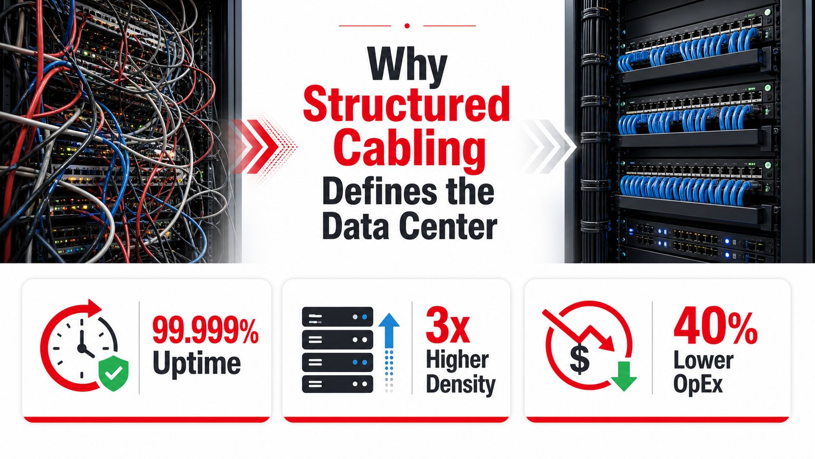
The first bad cabling decision usually doesn't fail on day one. It shows up later, when a change order needs three extra patching steps, a tech can't trace a fault without unseating half a row, or a cable bundle starts stealing air from the cold aisle. In a data hall, those problems are not cosmetic. They become uptime risks, labor costs, and cooling penalties.
Core plant, not a cleanup task
A structured cabling system in a data center is the organized infrastructure that carries traffic between distribution areas and equipment, with the design already constrained by standards, pathways, and testing. That's a very different thing from the ad hoc cabling many people still picture when they hear “network install.” In hyperscale builds, the scale makes that distinction impossible to ignore. According to research summarized by The Network Installers and attributed to Astute Analytica, a single hyperscale data center can require about 2.6 million feet of single-mode fiber, around 190,000 Cat6A copper drops, and roughly 4,500 MPO-24 fiber trunks. The Network Installers' structured cabling statistics make the point plainly, the cabling plant is huge enough to function like mechanical or electrical infrastructure.
That scale also changes what project owners should care about. If you wait until the white space is already full, you've already lost the chance to optimize tray routes, patch field access, and diversity paths. The primary design question is not “Can we fit the cables in?” It's “Can we keep the room operable when the next build wave lands?”
Practical rule: If a cabling change forces a tech to unpatch critical links just to reach the new one, the topology is already too expensive to operate.
The decision set that matters early
The project team should treat cabling as a layered system, not a single line item. The layers are straightforward, but they have to be designed together.
- Standards and performance targets: Define what has to be proven at acceptance, not just what parts get purchased.
- Topology: Decide how much hierarchy the workload needs, and where zones should be collapsed.
- Media: Match fiber and copper to distance, speed, and lifecycle headroom.
- Pathways: Keep airflow, access, and bend radius intact from day one.
- Lifecycle: Plan for labeling, documentation, and rework before the first panel is mounted.
That mindset turns cabling into a front-line design conversation. It also keeps the team from treating the network layer as something to “clean up later,” which is usually how expensive rework begins.
The Standards That Actually Shape Your Cabling
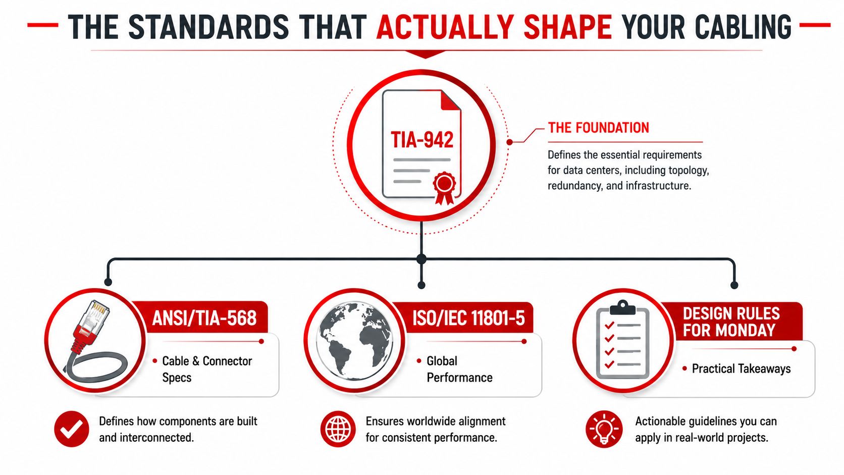
Standards matter in data centers because they turn cabling from a vendor promise into a testable system. ISO/IEC 11801-5 explicitly covers balanced copper and optical fiber cabling for data-center computer room spaces, along with link and channel performance, implementation options, component performance, and verification procedures. In other words, the standard is not just telling you what to install. It's telling you how the system has to behave and how that behavior gets proven. ISO/IEC 11801-5 matters because it forces repeatable acceptance across vendors and geographies.
What each reference really does
TIA-942 is the document many reach for when they need a data-center-specific physical infrastructure framework. It pushes you toward a documented topology with named distribution areas, redundancy awareness, and a design that can be audited instead of guessed at. ANSI/TIA-568 is the cleaner reference when the argument is about cable and connector specifications, because it helps define the media rules instead of the room layout.
ISO/IEC 11801-5 comes in when the discussion needs to hold up across international deployments or when the acceptance language has to be tied to a globally recognized cabling architecture. If you're comparing practices across sites, that distinction matters. The data hall in one country may have the same switches as another, but the acceptance test shouldn't depend on a local installer's habits.
For a practical summary of how these standards interact, it's worth reading the industry explanation at Southern Tier Resources' data center cabling standards guide. Use it as a bridge between the formal documents and the decisions people argue about on site.
The clauses worth citing in design review
The useful move in a review meeting is to ask for documented topology, defined media categories, and link or channel verification. Those three demands cut through a lot of noise. If a proposal can't show how the cabling will be verified, you don't have a completed design, you have an assumption.
Design takeaway: Standards don't make cabling good by themselves. They make bad choices easier to prove before they become outages.
That's the reason standards belong in the first RFP draft, not the closeout package. They set the terms of the build, and they give you the language to reject shortcuts before they harden into field reality.
Topologies and Zones From MDA to AI Fabrics
The classical structured cabling model still works well in many enterprise halls because it creates order, serviceability, and a predictable fault domain. The named zones, MDA, IDA, HDA, ZDA, and EDA, are the familiar way standards describe that order. In a clean hierarchical design, core gear lives at the top, distribution fans out through intermediate spaces, and equipment connections land at the edge.
Where hierarchy still earns its keep
The hierarchy helps when the room changes often, but not constantly. If multiple teams need to patch, trace, and reroute the same hall over time, the structure keeps the work comprehensible. It also gives you clean boundaries for documentation, access control, and troubleshooting.
That said, the hierarchy is not automatically the right answer for every workload. As AI and GPU clusters push denser east-west traffic and faster reconfiguration, the more direct spine-leaf model starts to make operational sense. Instead of preserving every historical layer, teams collapse some zones to reduce hops, shorten patching paths, and cut the amount of stranded cable sitting between active devices.
When less hierarchy is the better trade
The signal to simplify is usually workload, not ideology. If you're building a hall where port speed is rising, rack density is climbing, and the deployment pattern shifts often, extra intermediate patching can become a liability. You pay for it in insertion loss, troubleshooting time, and plain physical clutter.
A cabling plan that looks elegant on paper can still be wrong for a GPU pod that gets re-cabled every time the cluster layout changes.
That's why the right topology depends on how the environment behaves. Classical structured cabling is still a strong fit for general enterprise zones and many mixed-use halls. AI-oriented facilities often need something flatter, with shorter paths and fewer cross-connects.
The practical question is simple. Does the workload reward flexibility, or does it punish extra hops? If the answer is the second one, the design should drift away from a textbook hierarchy and toward a more direct fabric.
The industry conversation around AI cabling design is already moving in that direction, which is why many operators are rethinking how much of the old distribution model they really need. The video below shows how that architectural thinking is changing in practice.
Choosing the pattern without guessing
A good rule is to start with workload behavior, not with the prettiest diagram from the last project. If the room needs frequent reconfiguration and dense east-west traffic, collapse hierarchy where possible. If the site is a broader enterprise hall with mixed services and slower change cadence, the classical zone model still buys you clarity and operational stability.
The mistake is pretending both approaches are interchangeable. They're not. One is optimized for structure and control. The other is optimized for speed, density, and fewer physical transitions.
Fiber Versus Copper, Connectors, and Real Material Scale
Hyperscale cabling becomes concrete when you look at what a single build can consume. The numbers from Astute Analytica, as summarized by The Network Installers, are hard to ignore, 2.6 million feet of single-mode fiber, 190,000 Cat6A copper drops, and 4,500 MPO-24 fiber trunks in a single hyperscale data center. That isn't finishing material. That's a major infrastructure package, and it explains why media selection is a core engineering choice, not a procurement detail. Structured cabling statistics make the scale visible.
Picking the medium by job, not habit
Single-mode fiber is the right answer when you want long reach and future headroom. It's the default backbone choice when you want to avoid repainting the design every time port speeds move again. OM4 or OM5 multimode still has a place in shorter high-speed links where distance and transceiver economics work in its favor. Category 6A copper is the sensible choice for shorter horizontal runs, server access, and places where you need a simple, well-understood channel.
That leads to a basic selection logic. Use copper when the run is short enough and the use case is stable. Use multimode when the distance and application fit. Use single-mode when you want backbone flexibility and a longer planning horizon.
Connectors follow density and service pattern
MPO-24 trunks dominate the backbone conversation because they pack a lot of fiber into a form factor that makes high-density routing manageable. In the patch field, LC remains common because it's familiar and practical for many operator workflows. SN also matters in newer high-density environments where the connector footprint has to support more channels per rack unit.
The connector choice isn't just about what fits. It's about what the technician can terminate, inspect, and trace cleanly without turning the patch field into a failure point. The farther you get from the backbone, the more serviceability matters.
Here's a practical reference point for copper use in access-layer work. If you want a plain-language explanation of distance and capability, what Cat6 supports at 100 metres is a useful companion read for non-backbone planning.
| Use Case | Recommended Media | Typical Connector | Reach / Notes |
|---|---|---|---|
| Backbone between major distribution areas | Single-mode fiber | MPO-24, LC, SN | Best when you need long reach and future headroom |
| High-speed short links inside a hall | OM4 or OM5 multimode | LC, MPO | Useful when distance is shorter and density matters |
| Server access or horizontal runs | Category 6A copper | RJ45-style copper termination | Best for shorter, stable channels |
| Dense patch field where space is tight | Fiber focused layouts | LC or SN | Prioritize footprint and traceability |
Practical rule: Pick the media that matches the longest useful lifecycle of the space, not the cheapest cable reel on the quote.
That approach keeps the backbone from being rebuilt every time the compute layer changes. It also keeps the copper where it still makes operational sense, instead of forcing fiber everywhere just because the room feels modern.
Pathway, Cable Management, and the Airflow Trade-Off
Cabling density is a cooling issue as much as a network issue. If the bundles are bulky, poorly routed, or allowed to spill into airflow paths, the room pays for it in thermal inefficiency and maintenance friction. Neutral technical guidance on cable routing emphasizes avoiding airflow interference, using blanking panels, brushes, and grommets, and respecting bend radius and pull-distance limits, because cable bulk can compromise enclosure efficiency. STL's technical guidance is useful here because it connects routing choices to cooling behavior instead of treating them as separate disciplines.
Pathways that help or hurt the room
Ladder rack gives you a very different operating profile than basket tray. Overhead distribution usually protects the underfloor plenum, while underfloor routing can become a problem if congestion grows unchecked. Neither approach is automatically better. The right answer depends on how much service access you need, where the cooling paths move, and how often the cabling has to change.
A path that's easy to install can still be expensive to live with if it blocks service access or crowds out air movement. The technician who adds a new jumper without thinking about tray fill can create a hot spot that doesn't appear in the ticketing system, only in the thermal alarms later.
The practical threshold is visual and operational
There isn't a universal safe fill level that works for every room, and pretending there is usually leads to bad design behavior. The better threshold is operational, if a tray is so full that a tech can't add or trace a cable without compressing the bundle, the layout is already too congested. If cables start bowing into the air path or hanging below the intended containment plane, the routing has become a thermal problem.
Field rule: If cable management makes a row harder to cool or harder to service, it's no longer management, it's obstruction.
For most builds, the fix is not a full redesign. It's usually simpler, higher-mounted tray routes, cleaner separation from power pathways, and fewer giant service loops. Overhead patching often works well because it keeps the floor clear and makes future moves more visible.
For a practical solution set on containment, labeling, and route discipline, the internal guide at Southern Tier Resources' cable management solutions is a solid reference. The important part is not the product category, it's the idea that cable bulk has to be treated as part of the thermal design.
The shortcuts that hurt later are predictable. Oversized loops, crowded underfloor runs, and sloppy separation from busways all make maintenance harder and cooling less stable. Once you've seen a row that starts to breathe badly because of cable mess, you don't forget it.
Integrating Cabling With Power, Cooling, and Redundancy
Cabling, power, and cooling are one white-space system. They share the same geometry, the same access constraints, and the same failure consequences when one scope is designed in isolation. That's why diverse routing, A/B feed separation, and cooling containment need to be considered together, not handed off from one subcontractor to another after the layout is already frozen.
Design the three paths as one system
Redundant power paths only stay useful if the cabling layout doesn't force them to cross in the wrong places. Diverse routing needs physical discipline. If both cable paths share the same tray pinch point, the design isn't diverse enough to matter in a real incident.
The same logic applies to cooling. Hot and cold aisle containment can only work if cable routes don't spill into the containment boundary or create service obstacles that get removed later by whoever needs access fastest. Clean cable routes often prevent electrical rework because they preserve access for both power and network crews.
The choice of N, N+1, or 2N redundancy should be reflected in the route drawing, not just in a narrative note. If a drawing says the site is redundant but doesn't show physically distinct paths, it's not auditable.
What should appear on the drawing
- A/B path labeling: Mark which cable and power paths belong to each side.
- Zone boundaries: Show where one zone ends and the next begins.
- Crossing points: Identify where paths intersect, then minimize those points.
- Service access: Keep room for maintenance without forcing live-path disturbance.
- As-built clarity: Capture the final route, not the intended route.
That matters because the as-built set becomes the maintenance record. If the documentation is vague, the next team will make assumptions in the field, and those assumptions will be wrong at the worst possible moment.
One practical partner that can handle both cabling and broader facility integration is Southern Tier Resources, especially on data-center fit-outs where structured cabling, connectivity, and build coordination have to line up with the rest of the infrastructure. That kind of integrated delivery is useful when the layout, the power plan, and the network plant all have to be reconciled under one schedule.
Testing, Documentation, and Common Pitfalls You Can Avoid
A structured cabling system isn't done when the last patch cord is plugged in. It's done when the links are certified, the polarity is correct, the labels make sense to someone who wasn't on the install crew, and the as-built set matches the room that was built. If those pieces are missing, the system will still look organized for a while, but it won't be dependable when the first real maintenance window comes around.
What defensible acceptance looks like
For fiber, the test plan has to cover the basics that determine whether the link will operate cleanly over time, not just whether light passes. That means link and channel performance, polarity, continuity, and insertion loss need to be checked. For copper, the same logic applies, because a tidy bundle that fails certification still becomes a support ticket.
The useful habit is to test to the standard, label to the standard, and document to the standard. That way, when a fault appears six months later, the team can compare the live room to a known baseline instead of starting from scratch.
For a practical fiber testing workflow, the guide at Southern Tier Resources' fiber optic cable testing page is a relevant reference. Use it as a field-oriented complement to the certification paperwork.
The shortcuts that cause slow-burn failures
The recurring mistakes are easy to name because they keep showing up in different buildings.
- Oversubscribed trays: Too much material in the pathway makes cooling and service harder.
- Mixed polarity habits: If polarity isn't controlled, troubleshooting becomes a chase.
- Unlabeled patch fields: A clean-looking rack with no traceable labels is still a liability.
- Weak as-builts: If the records don't match the room, maintenance will be slower and riskier.
The contrarian point matters most in AI-heavy builds. More patching is not always better. Extra hierarchy adds insertion loss, adds troubleshooting overhead, and gives operators more places to make mistakes. In dense GPU environments, shorter and more direct architectures can be the better operational choice because they reduce the amount of cabling that has to be touched every time the workload changes.
A good cabling design is the one that stays understandable under pressure. That's the core test.
If you're planning a data center fit-out, retrofit, or cabling audit, Southern Tier Resources can support the design, installation, testing, and documentation work that keeps the white space maintainable after handoff. Visit Southern Tier Resources to talk through a structured cabling plan that fits your power, cooling, and workload requirements.