A grounded ANSI/ESD S20.20 program, combined with a personnel grounding path that addresses the complete operator-to-reference interface, is the practical foundation of static discharge prevention for telecom and data-center work. A wrist strap or floor mat alone is insufficient if the person, cart, ladder, cable component, or work surface remains electrically floating.
You're standing in a temporary build area with a rack open, fiber hardware still in its packaging, and another crew moving ladders behind you. The bench has an ESD mat, someone says the rack is grounded, and the transceiver looks like it can be installed in seconds. That's exactly where good intentions become unreliable controls.
Static discharge prevention isn't about waiting to feel a spark. A discharge can be invisible, too brief to notice, and still damage an interface or create a defect that surfaces after handoff. The field standard is simple: control how charge is generated, give it a defined path to dissipate, and verify that the path works under the conditions in which the crew works.
Why Static Discharge Still Breaks Telecom Gear
A fiber splice fails weeks after installation. The technician recalls touching ground before handling the transceiver, so the fault is assigned to configuration, cabling, or the device itself. That conclusion is unsafe. Touching a grounding point does not prove that the worker, footwear, floor, rack, tool, and component shared the same reference at the moment of contact.
Temporary telecom builds create hidden gaps. A rack may be bonded while a portable bench floats. ESD footwear may be approved, yet the temporary flooring has never been qualified with it. A crew may have a written ANSI/ESD S20.20 process, while ladders, carts, packaging, and rushed handoffs remain outside enforcement.
Static discharge usually produces one of three outcomes:
- Immediate failure: A component stops working during installation or testing.
- Latent damage: The equipment passes initial checks but fails later in service.
- Ignition: A discharge ignites flammable liquids, gases, or combustible dust during construction, maintenance, or fuel-related work.
NASA's electronics failure analysis reviewed 283 microcircuit failure reports, with 232 reports categorized for analysis and 35 failures identified as electrostatic-discharge failures in the reviewed dataset covering January 2001 through September 2013. The report describes ESD as severe, localized damage on a semiconductor die. A technician may see no mark while leaving a weakened component behind. (NASA's ESD failure analysis)
The three failure paths
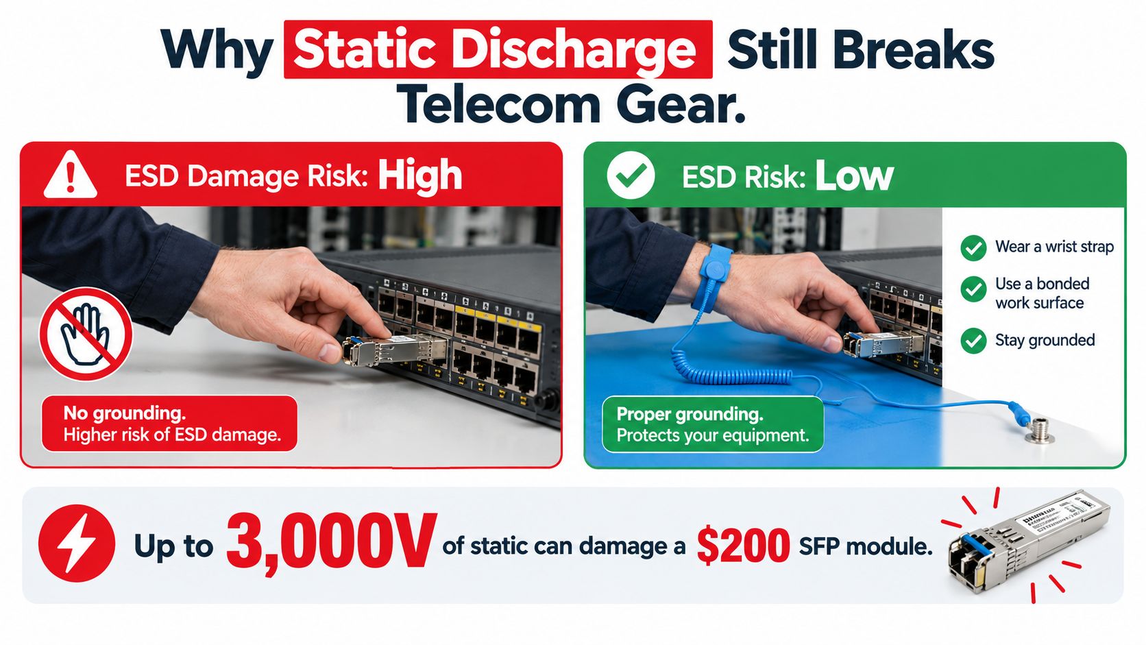
Immediate damage is easiest to find. A transceiver may fail during bring-up, a sensitive interface may become intermittent, or a board may show symptoms that send the crew toward unnecessary replacement.
Latent defects take longer to expose. Acceptance testing can pass, then thermal cycling, handling, or normal operating stress reveals instability. With no visible evidence of the original event, teams often blame firmware, configuration, or an unrelated cable fault. Troubleshooting expands, while the failed control at the work area remains unexamined.
Ignition requires a separate response. The NFPA Fire Protection Research Foundation reviewed 89 documented static-related incidents, and more than 20% identified negligence as the primary contributing cause. That finding points to gaps in procedures, training, inspection, or consistent control use, rather than awareness alone. (NFPA Static Electricity Incident Review)
| Failure mode | Typical symptom | Likely cause |
|---|---|---|
| Immediate hardware damage | No link, failed startup, or failed test | Discharge reached an exposed interface or device |
| Latent component damage | Intermittent operation or later field failure | Component weakened during handling |
| Ignition event | Spark, fire, or explosive incident | Charge accumulated near an ignitable atmosphere |
| Repeat handling exposure | Multiple unexplained failures across a crew | Controls exist on paper but are not enforced |
The working objective is a verified electrostatic-control system. It must keep the operator, hardware, tools, racks, packaging, and temporary equipment within the same controlled path, including the conditions present on the actual job site.
Setting Up Grounding and Bonding Before You Touch Hardware
Start with the reference point, not the wrist strap. An ANSI/ESD S20.20-style program first defines whether the work area uses equipment or AC ground, an auxiliary ground, or an equipotential bonding system. Every person and conductive object then connects to that defined reference. (ANSI/ESD S20.20 guidance)
A temporary telecom room often has several possible grounds. The rack may be bonded to the building system, the bench may use a common-point ground, and a portable generator or construction panel may introduce a different reference. Don't assume those points are interchangeable. Confirm the approved grounding architecture with the responsible electrical or ESD authority before building the work area.

Build the physical path
Bond the conductive work surface, rack, tools, cable-handling equipment, carts, and other conductors to the chosen reference. Bond the person through a grounded wrist strap when seated work requires it, or through a qualified footwear-and-flooring system when movement is part of the task.
The most common field mistake is grounding only the bench. The technician is standing on an insulating floor covering, the cart has rubber wheels, a ladder is nearby, and a shielded cable component is resting on plastic. The mat may test correctly while the actual handling path remains floating.
Practical rule: If a conductive object can move into the work zone, either bond it, remove it, or verify why it isn't part of the control plan.
Nonconductive materials need special treatment. An insulator can't discharge merely because someone connects a ground lead to a nearby bench. Control it with spacing, ionization, conductive or static-dissipative replacements, and approved handling methods.
Before accepting a temporary work area, ask:
- What is the approved grounding reference?
- Which conductive surfaces and mobile equipment are bonded?
- How are personnel grounded during seated and standing work?
- What happens when the crew changes boots, floor covering, or tools?
- Where are compliance records and test results stored?
For general electrical grounding terminology and site-level earthing context, DLG Electrical's DLG Electrical earthing guide is a useful reference. It doesn't replace the project's ESD control plan, but it can help new technicians understand why a physical connection isn't automatically a verified equipotential path.
The video below reinforces the basic relationship between a technician, the grounding point, and the equipment being handled.
Choosing the Right ESD PPE and Tooling
PPE must match the task and the control architecture. A seated technician installing a component at a verified ESD workstation faces a different exposure from a crew member carrying electronics across a temporary build floor, where the approved ground may be unclear and enforcement may be inconsistent.
For seated handling, a grounded wrist strap is usually the most direct personnel-control method. ANSI/ESD guidance expects seated operators to use one. If the process cannot support that requirement, document the reason in a tailoring statement. An informal agreement between technicians does not establish control.
Standing and mobile work require a qualified footwear-and-flooring system. The complete path runs from the operator, through the footwear and floor, to the approved ground reference. A floor that passes by itself does not prove that a particular boot, overshoe, or worker movement will maintain the same path.
Compare the common controls
- Wrist strap: Best for seated work at a bonded station. Connect it to the defined reference and keep it connected during handling.
- ESD footwear and flooring: Suitable for standing and mobile tasks after the complete person-to-ground path has been qualified.
- Smock or garment: Controls charge from clothing and limits contact between ordinary fabrics and sensitive assemblies. It does not replace personnel grounding.
- Dissipative mat: Provides a controlled path for the work surface when correctly bonded. It does not ground a nearby cart, ladder, or worker automatically.
- Conductive cart: Useful for moving sensitive hardware when the cart is bonded and its wheels do not isolate it from the work-area reference.
- Ionizer: Helps control charge around required insulators that cannot be grounded. It does not replace bonding for conductive objects.
- Grounded tooling: Soldering stations, hand tools, fixtures, and cable aids should be selected and verified for the task, rather than treated as ordinary shop equipment.
Footwear-and-flooring qualification should include resistance measurement through the operator, a walking test for peak body voltage, repeat testing for each footwear style, and low-humidity testing around 12% relative humidity and 23°C, as described in the ESD Association footwear and flooring guidance.
Record the footwear used on the job. A crew can qualify one work boot, then substitute an insulating overshoe or winter boot. The floor may still pass, while the operator interface has changed. In a temporary telecom build, that substitution needs review before the replacement reaches the controlled work area. Each tool, cart, garment, and grounding accessory also needs a clear owner and inspection status, so the written ANSI/ESD S20.20 control is enforced on site rather than left as a paper requirement.
Fiber and Electronics Handling Checklists
A module can leave approved packaging in good condition and still be exposed within seconds. Before opening the bag, move the job into the controlled area, confirm the worker's grounding path, and clear the route to the rack. The package limits exposure during storage and transport. It does not control the work surface, clothing, tools, or nearby equipment after opening.
Before handling fiber hardware
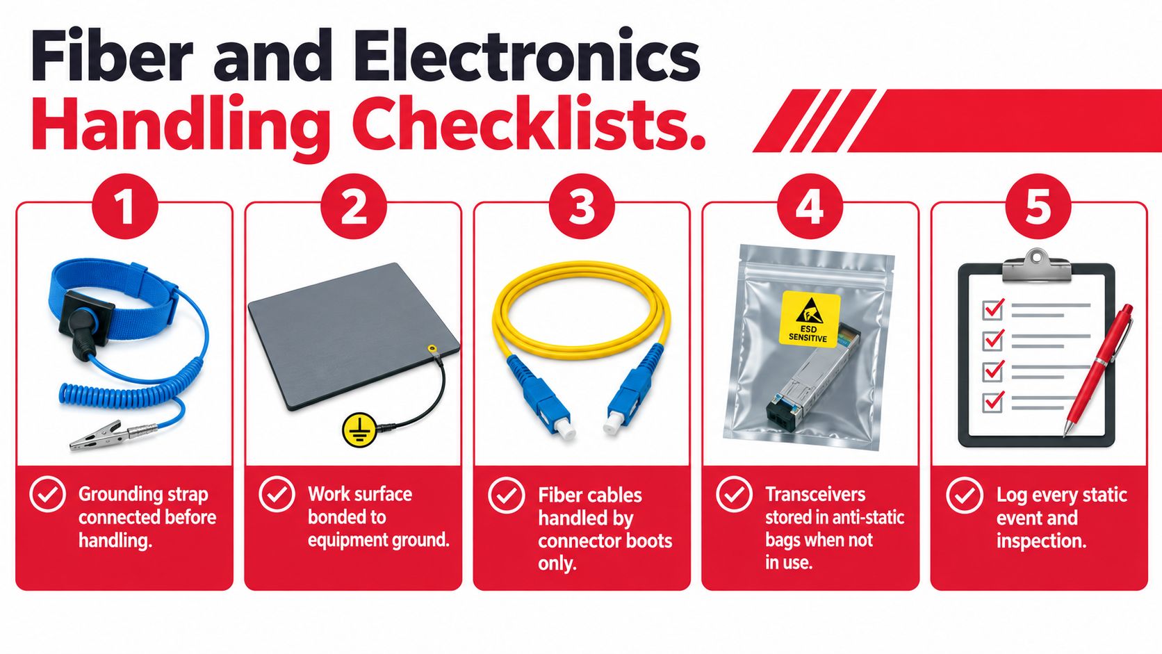
- Prepare the area: Remove loose plastic, foam, tape, cardboard, and other insulators from the immediate work surface. In a temporary telecom build, check behind the station as well. A jacket, ladder, or packaging lid can become the surface used in a hurry.
- Verify personnel grounding: Connect the wrist strap, or confirm that the qualified footwear-and-flooring path matches the footwear worn. A passing floor does not qualify a replacement overshoe or winter boot.
- Bond the surface: Confirm that the mat, rack, fixture, and conductive tray share the approved reference. Do not assume a nearby cart or ladder is bonded because the station is.
- Inspect packaging: Keep unused modules in approved ESD packaging. Do not place them on ordinary foam, cardboard, or a plastic lid.
- Plan the movement: Set the route from package to rack before opening the bag. Avoid carrying an exposed device through an uncontrolled construction zone.
Record the footwear, garments, cart, and grounding accessories used at the station. Assign each item an owner and inspection status. That simple record helps enforce ANSI/ESD S20.20 controls in temporary builds, where qualified equipment is often substituted without review.
During termination and splicing, hold fiber cables by the connector boot or approved strain-relief area. Keep shielded cable components off insulating surfaces, and do not rest an exposed transceiver on a ladder, jacket, or tool pouch.
Before handoff
Check connector condition, seating, labels, and test results. Quarantine any component that was dropped, placed on an uncontrolled surface, or handled after a grounding failure. Do not return it to stock on assumption alone.
The handling-stage warning in NASA's electronics parts and packaging bulletin applies beyond final testing. Receiving, storage, installation, maintenance, splicing-related electronics work, and field service can all expose sensitive parts.
For component movement and storage, this packaging guide for plant managers offers practical context for selecting anti-static packaging. Packaging supports the process, but it cannot correct a floating worker or an unverified surface.
Log failed strap tests, damaged packages, uncontrolled contact, and unbonded carts. A short factual record gives the next technician something to act on.
Testing and Verifying ESD Controls
An ESD program earns trust at the work point, not in a binder. Begin with basic continuity checks, then test the full grounding path where people, footwear, flooring, tools, and equipment interact.
Before sensitive hardware is handled, use a wrist-strap tester to confirm continuity. Check the common-point ground and work surface against the approved reference with calibrated equipment. If the station uses a dissipative floor, test the installed system. A product specification cannot show whether adhesive, seams, floor coverings, or construction changes have altered performance.
Test the system the crew uses on site
Temporary telecom builds often pass an individual control while the combined path fails. Measure resistance from the operator through the footwear and floor to ground. Follow with a walking test to identify peak body voltage. A person can pass a stationary check yet generate charge while moving, changing boots, or crossing a different floor surface.
Qualify every footwear style used by the crew. Include site conditions that affect the result, particularly low humidity and seasonal changes. As noted earlier, the ESD qualification guidance uses 12% relative humidity and 23°C conditions, which can expose weaknesses hidden by a comfortable indoor test.
A compliant floor is not a compliant person-to-ground path until the operator, footwear, movement, and ground reference have been tested together.
Keep verification defensible
Record the method, instrument identity, calibration status, operator, location, footwear, floor system, environmental conditions, and result. A calibrated meter without this record cannot show what was tested or whether the result still applies after the build changes.
For ionizers, verify output and balance according to the equipment procedure. Check placement near the insulating materials that create the charge problem. For carts and ladders, test the conductive path after wheel replacement, coating work, painting, or repairs. A grounded-looking frame can remain electrically isolated through a finished surface or damaged bonding point.
Recheck controls after floor coverings move, common-point leads are unplugged, racks are relocated, or temporary power equipment changes. In temporary builds, ANSI/ESD S20.20 can be satisfied on paper while site enforcement fails at the handoff between crews. Record the result at the station and stop use until an unverified path is corrected.
Training Crews and Managing Incidents
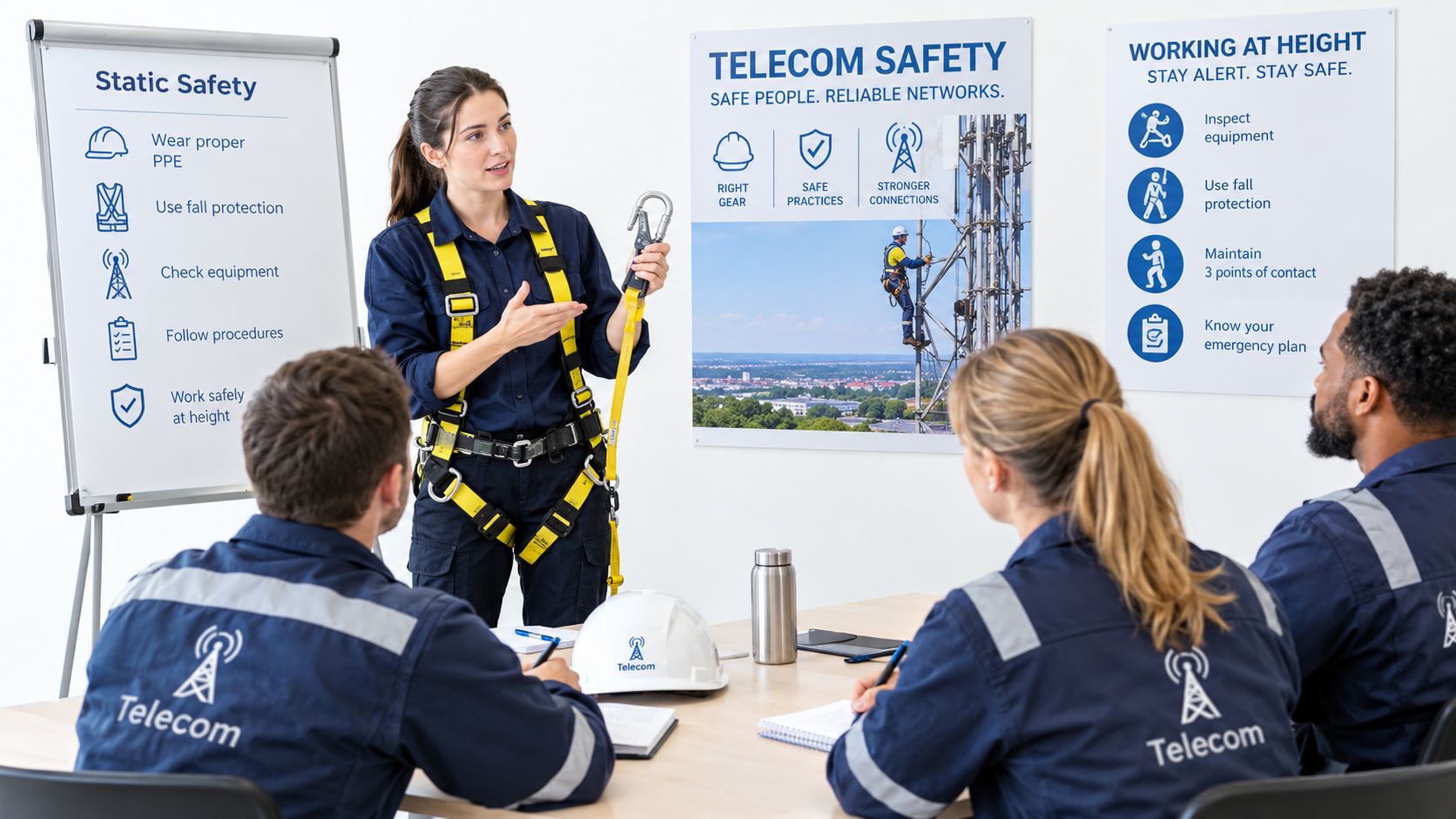
Static discharge controls must hold during a rushed installation, not only during classroom practice. Train splicers on connector and transceiver handling, rack technicians on personnel grounding and bonding, inspectors on the evidence they must record, and supervisors on stopping work when the control path is unavailable. In temporary telecom builds, ANSI/ESD S20.20 can look satisfied on paper while enforcement fails during a crew handoff.
Use the actual site for toolbox talks. Show the grounding post, bonded mat, approved footwear, ESD packaging location, and equipment route. Have one technician perform the pre-work check while another identifies conditions that would invalidate it. Include footwear–flooring qualification, the ground reference, and the effect of movement, especially where low humidity or seasonal changes can alter results.
Make incidents useful
When a component fails or behaves intermittently, preserve the facts:
- Identify the component: Record the part, serial number, location, installer, and handling time.
- Protect the evidence: Quarantine the component and packaging instead of returning them to stock.
- Reconstruct the path: Record footwear, flooring, wrist strap, work surface, tools, cart, and uncontrolled contact.
- Check conditions: Record available humidity and temperature, plus nearby construction activity.
- Compare records: Review tester results, inspection logs, training status, and recent work-area changes.
- Correct the system: Repair the failed control, retrain the crew, and verify the corrective action.
Avoid turning every event into a blame exercise. The negligence finding from the NFPA incident review cited earlier shows why procedures and supervision matter alongside individual behavior. A floating ground, an unqualified shoe and floor combination, or a disconnected common-point lead can defeat a technician who follows the written steps.
For dispersed crews, digital records make site-specific procedures easier to assign and audit. Providers of custom compliant training workflows can help organize role-based learning, signoffs, and refreshers around the tasks technicians perform. Record failed checks at the station, stop use until the path is corrected, and require the next crew to acknowledge the handoff.
Environmental Risks and What Humidity Really Controls
Humidity helps, but it isn't a universal fix. Moisture can increase surface conductivity and reduce charge accumulation, while low humidity makes charge buildup more likely. That doesn't make “raise the humidity” a complete telecom or data-center strategy.
Guidance varies between operating ranges such as 40–50% relative humidity, 50–60%, or levels above 30%, which is one reason facility teams shouldn't copy a single target without considering the room, equipment, process, and building systems. The practical question is whether humidity control reduces the specific charge mechanism without introducing a larger facility risk.
Excess moisture can create condensation, corrosion, HVAC complications, and operational concerns. A live data-center floor also has different requirements from an electronics bench, a battery area, or an outdoor telecom enclosure. Humidifying an entire facility to solve a localized packaging or clothing problem may be the wrong trade-off.
Use a layered environmental strategy
Set a normal operating band for the specific work area, then define action thresholds that trigger investigation. Pair environmental monitoring with:
- Personnel checks: Verify wrist straps or the complete footwear-and-flooring path.
- Grounding checks: Inspect common-point grounds, racks, carts, ladders, and temporary equipment.
- Surface controls: Confirm mats, fixtures, bins, and packaging remain suitable and bonded.
- Ionizer checks: Use local ionization where required insulators continue generating charge.
- Process controls: Reduce unnecessary friction, sliding, rapid material movement, and uncontrolled packaging contact.
Static-discharge guidance for telecom and data-center environments supports this risk-based approach, pairing continuous environmental monitoring with periodic verification of wrist straps, footwear, flooring, common-point grounds, and ionizer performance. (Electrostatic handling precautions)
A controlled ESD work area doesn't need the same treatment as an entire production room. Keep sensitive handling inside a defined protected zone, monitor conditions there, and don't let a humidity reading create false confidence about an unbonded operator or floating cart.
Southern Tier Resources delivers end-to-end telecom and data-center infrastructure services, including fiber deployment, splicing, testing, structured cabling, and maintenance with a focus on safe, reliable execution. If your project needs field teams that can integrate static discharge prevention into real construction and fit-out work, visit Southern Tier Resources to discuss your infrastructure requirements.