A familiar problem shows up the same way in very different environments. A carrier aggregation site starts dropping packets during peak hours. A hyperscale row goes noisy after a new cluster comes online. An enterprise core that looked fine on paper suddenly can't absorb east-west traffic without queueing, retransmits, and ugly application complaints. The symptoms vary, but the diagnosis is usually the same. The network has outgrown copper-era assumptions.
That's when the fiber optic network switch stops being a line item and becomes the control point for the whole design. Port speed matters, but it's rarely the only issue. Key decisions reside in the details most datasheets gloss over: how uplinks are oversubscribed, what the transceiver mix does to heat, how redundancy is wired, whether the switch fabric can forward at line rate under stress, and how operations teams will support the platform six months after deployment.
Engineers who work on telecom and data center infrastructure already know the basics. What tends to get missed is the operational reality between “supports fiber” and “runs reliably at scale.” That gap is where projects drift into avoidable problems: mismatched optics, stranded ports, poor airflow, overloaded power shelves, bad failover assumptions, and procurement driven by headline speeds instead of deployable architecture.
Introduction The Modern Network's Light-Speed Heart
At 2 a.m., the alerts usually do not say "bad switch choice." They show up as rising interface errors, optics running hot, a fabric that looks fine at half population and unstable at full load, or a failover event that pushes traffic into the wrong bottleneck. By the time those symptoms appear, the fiber optic network switch is no longer a procurement item. It is part of the facility's power, cooling, and resiliency design.
That is the part buyers miss when they focus on port counts and headline speeds. In telecom sites and hyperscale rows, optical switching decisions carry second-order effects that matter just as much as throughput. A dense 100G or 400G build changes airflow requirements. Mixed optics increase sparing complexity. Redundant power feeds only help if the upstream design and maintenance procedures match them. The switch has to fit the traffic model, but it also has to fit the rack, the thermal envelope, and the way the operations team handles faults.
The packet-forwarding model still matters. Teams that need a quick refresher on switching behavior can review this packet switching guide for MSPs. In fiber deployments, though, the practical question is not whether packets can be switched. It is whether they can be switched at line rate, under sustained load, with predictable latency, and without turning the row into a cooling problem.
One number from operations planning makes that clear. According to the Uptime Institute Global Data Center Survey 2023, power density keeps rising in many facilities, and that changes what "fits" in a rack even before compute is installed. For fiber switch deployments, that translates into a straightforward constraint. Every transceiver, fan profile, and power supply decision competes with the same finite thermal budget.
Three checks separate a clean deployment from an expensive retrofit. Verify that the forwarding architecture matches real east-west and north-south traffic patterns. Verify that power and cooling assumptions still hold when every intended port is populated with the optics you plan to use. Verify that redundancy is real at the system level, not just present on a feature sheet. If any of those checks fail, the optical switch becomes the point where performance, facilities, and operations start working against each other.
Deconstructing the Core Concepts of Fiber Switching
A fiber optic network switch does the same job as any other switch at a high level. It receives traffic from connected devices and forwards it only to the intended destination. What changes is the medium, the performance envelope, and the physical behavior of the network.
Why light changes the design
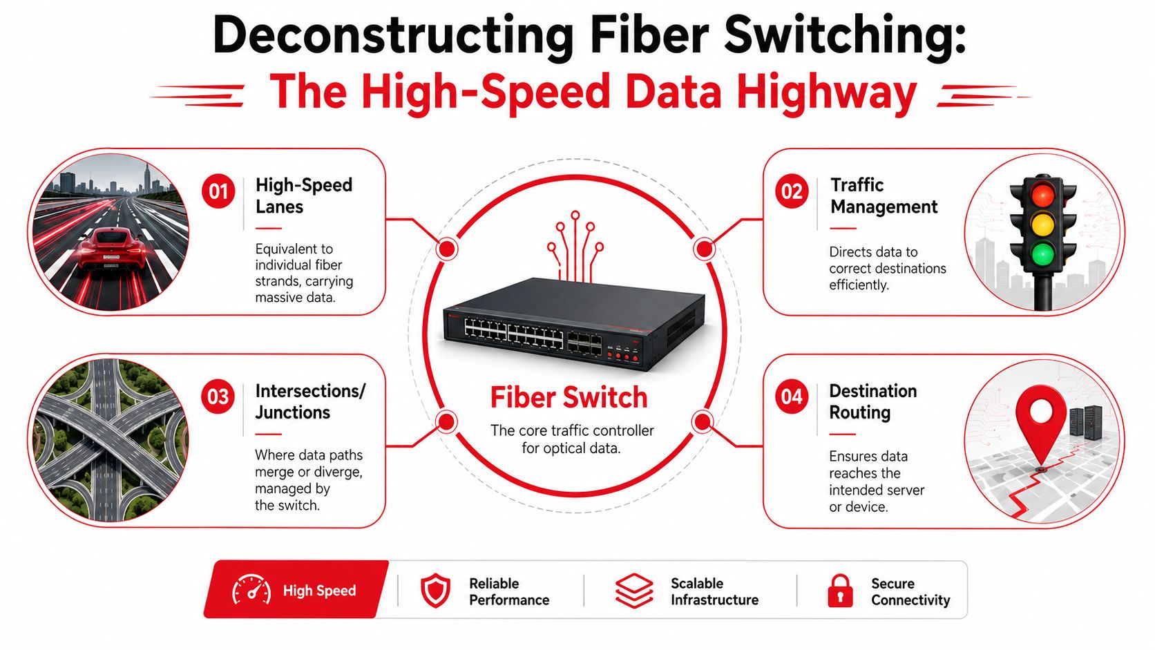
The best mental model is a highway interchange. Copper switching is like moving traffic through a city grid. It works, but every intersection adds friction, distance matters quickly, and electrical noise can create ugly edge cases. A fiber optic network switch behaves more like a controlled multi-lane interchange built for uninterrupted flow.
The reason is physical, not marketing. Fiber uses light signals instead of electrical signals. That gives it stronger bandwidth characteristics, lower latency behavior, and resistance to electromagnetic interference. In practice, that means more stable links in noisy environments and better performance where dense traffic is normal instead of occasional.
According to Todahika's explanation of how fiber network switches work, fiber optic network switches enable data transmission speeds of up to 100 Gbps, while traditional copper-based Ethernet switches typically support maximum speeds of 1 to 10 Gbps in standard enterprise deployments. That gap matters most in places where delay compounds quickly, including cloud workloads, streaming, and real-time analytics.
What the switch is actually doing
At the forwarding level, the switch still acts as a traffic controller. It learns where devices live, receives frames or packets, and sends them toward the right destination path. The difference is that optical links let the platform sustain heavier concurrent loads without forcing the designer into short-run compromises.
For a practical understanding of this:
- Fiber strands are lanes: Each link carries substantial traffic without the same distance and interference limitations common in copper-heavy designs.
- The switch is the interchange: It decides where traffic enters, exits, and converges.
- Buffers are merge zones: Good hardware absorbs bursts cleanly. Weak hardware creates contention and latency spikes.
- Uplinks are your long-haul routes: If uplink design is poor, local switching speed won't save the network.
A fast port doesn't fix a congested fabric. Engineers need to evaluate the whole traffic path, not just the optic in the faceplate.
For teams that want a refresher on how traffic forwarding logic evolved into modern switching behavior, this packet switching guide for MSPs is useful context. It helps frame why forwarding efficiency matters so much once optical links remove older transport constraints.
Where misunderstandings still happen
One recurring mistake is assuming “fiber switch” means “plug any fiber into it and the network is solved.” That's not how most production environments work. Optical transport, access handoff, and local switching each have different roles. A switch may terminate SFP-based interfaces cleanly, but it still has to fit into the larger design, including optical network terminals, transceivers, VLAN structure, and routing boundaries.
That's why successful deployments start with role clarity. Decide whether the switch is aggregating access, serving top-of-rack, acting as a leaf, providing transport handoff, or collapsing layers in a smaller site. Once that role is clear, the rest of the design gets easier.
Navigating Switch Architectures Ports and Interfaces
Most procurement mistakes happen at the faceplate. The chassis looks right, the quoted throughput seems acceptable, and the port count appears generous. Then the deployment starts and someone realizes the switch doesn't support the transceiver mix, breakout plan, or media type the design assumes.
Ports are physical, transceivers are translators
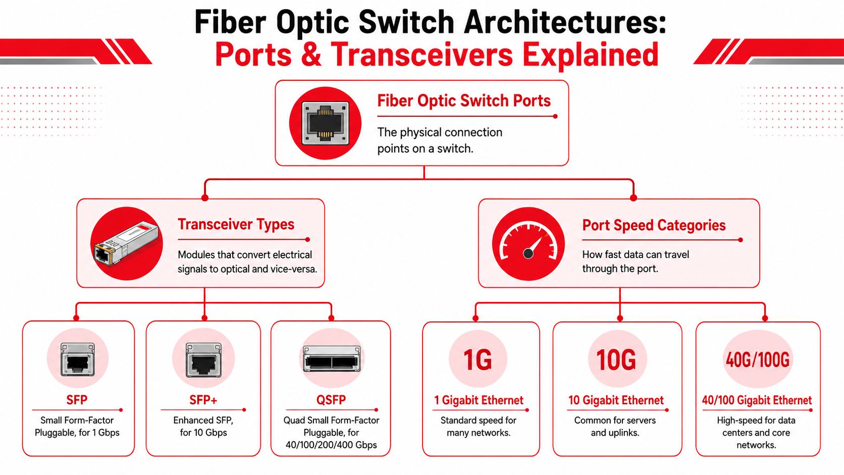
A useful analogy is to treat transceivers as universal translators. The switch port provides the electrical and logical interface. The pluggable module translates that interface into the optical characteristics needed for the fiber plant you're using.
According to Cisco's hardware notes on SFP-based switching, fiber optic switches utilize Small Form Factor Pluggable (SFP) ports to enable hot-swappable input/output devices like GBICs, linking Ethernet ports directly to fiber-optic networks and supporting longer-distance transmission with stronger signal integrity than copper-based Ethernet switches.
That hot-swappable design is one of the biggest operational advantages in production. It lets teams change optics without replacing the switch, but it also creates a trap. Modularity makes designs flexible. It doesn't make them foolproof.
Reading the common interface families
You'll usually see some mix of these categories:
| Interface family | Typical role in design | Practical note |
|---|---|---|
| SFP | Common for lower-speed fiber access and aggregation | Good for broad compatibility and simple uplink needs |
| SFP+ | Popular for server uplinks and distribution links | Often the sweet spot in mixed enterprise and telecom builds |
| QSFP | Used where higher-density uplinks matter | Helpful when you need consolidation and breakout flexibility |
| QSFP28 and similar high-speed variants | Common in data center core, leaf-spine, and dense interconnect designs | Useful, but they raise thermal and cabling discipline requirements fast |
The important point isn't memorizing acronyms. It's understanding that each pluggable family affects density, airflow, cable management, inventory strategy, and migration options.
Single-mode and multi-mode choices
The port and module combination also has to match the physical plant. That means deciding between single-mode fiber and multi-mode fiber based on the path you're supporting.
Use this simple decision frame:
- Choose single-mode when the deployment spans longer runs, campus backbones, metro extensions, or carrier-oriented transport segments.
- Choose multi-mode when the run is short, controlled, and typically inside a building or data hall where existing plant already supports it.
- Avoid mixed assumptions between structured cabling teams and network teams. A switch can be perfectly specified and still fail the rollout because the installed plant doesn't match the optics order.
- Validate cleaning and inspection workflow before cutover. Optical compatibility on paper won't overcome dirty connectors in the field.
For teams designing the physical topology before selecting hardware, a solid starting point is this overview of fiber optic network design. It's useful because architecture decisions upstream usually determine whether a switch platform will feel flexible or frustrating later.
The density trade-off nobody likes to talk about
Higher density looks efficient in a proposal. In a rack, it raises the operational difficulty. More pluggables in less space means tighter cable management, worse finger room for replacements, higher heat concentration around the port field, and more chances for accidental disturbance during maintenance.
Procurement warning: Don't buy the maximum port density your budget allows unless your airflow plan, patching discipline, and spare optics process are already mature.
Dense platforms are excellent when the operating model supports them. They're painful when the environment still relies on ad hoc patching and rushed after-hours changes. In that case, a slightly lower-density switch with cleaner serviceability often performs better over its actual lifespan.
Layer 2 and Layer 3 Functions in Optical Networks
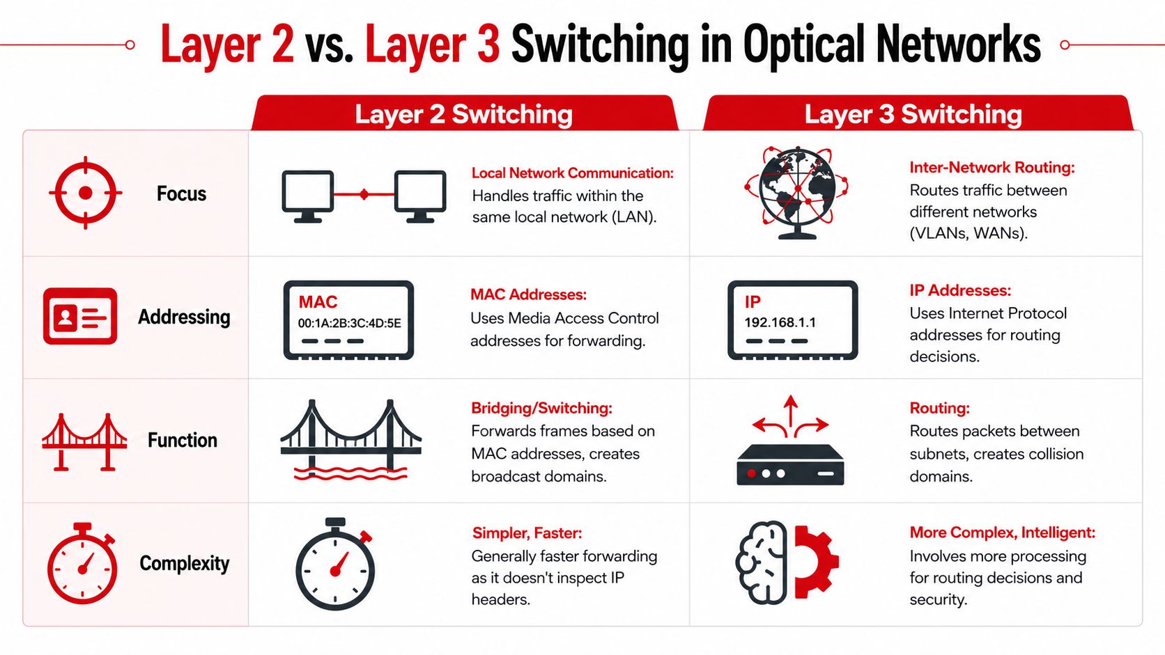
Once the hardware is selected, the next question is logical role. A fiber optic network switch can operate as a pure Layer 2 platform, a Layer 3 routing switch, or part of a mixed architecture. The optical medium doesn't change those fundamentals, but it does raise the stakes when traffic volumes grow.
Layer 2 as local delivery
Layer 2 switching is the local sorting facility. It forwards frames inside the same broadcast domain or VLAN using MAC addresses. In optical top-of-rack and aggregation use cases, that's often exactly what you want. It keeps forwarding simple and fast, especially when the rack or pod has a clear local boundary.
Layer 2 works well for:
- Top-of-rack aggregation where servers or appliances stay inside a tightly controlled local segment
- Access-layer optical handoff in facilities that need clean VLAN extension
- Simple east-west adjacency where routing complexity would add overhead without clear benefit
The risk is scale creep. Flat Layer 2 designs feel easy until they don't. Broadcast behavior, troubleshooting scope, and failure blast radius all get worse when local domains grow without discipline.
Layer 3 as inter-network coordination
Layer 3 switching is the logistics coordinator. It routes traffic between subnets and VLANs using IP decisions, which gives architects much tighter control over segmentation, policy, pathing, and fault isolation.
That makes Layer 3 the better fit for:
| Use case | Better fit | Reason |
|---|---|---|
| Server rack aggregation with minimal policy needs | Layer 2 | Keeps forwarding local and straightforward |
| Distribution or core switching across multiple VLANs | Layer 3 | Contains failure domains and routes between segments |
| Multi-tenant or policy-heavy environments | Layer 3 | Supports cleaner segmentation and traffic control |
| Smaller dedicated optical segments with one clear purpose | Layer 2 | Avoids unnecessary routing complexity |
What works in practice
Most production optical environments aren't purely one or the other. They use Layer 2 where adjacency matters and Layer 3 where containment matters. That's usually the right call.
Keep Layer 2 domains intentionally small. Use Layer 3 boundaries to control blast radius, not just to satisfy a textbook design pattern.
The common mistake is stretching Layer 2 further than operations can safely troubleshoot. Optical switching can carry large volumes cleanly, which sometimes hides poor segmentation until an outage turns a local issue into a widespread one. Layer 3 puts more intelligence into the switch role, but it often pays for itself the first time a fault stays contained.
High-Availability Deployment and Redundancy Patterns
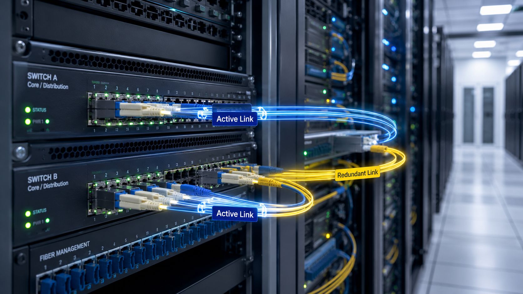
Redundancy isn't a box-checking exercise. In optical networks, it's the difference between a recoverable event and a long night. Hardware fails, optics go marginal, links get contaminated, maintenance windows slip, and traffic doesn't pause while teams diagnose it.
Why leaf-spine became the default pattern
For modern data centers and telecom-scale compute environments, leaf-spine remains the most practical architecture because it gives predictable paths and strong east-west capacity. Every leaf connects upward in a consistent way, so applications don't depend on one oversized core path to move laterally.
That consistency matters more than elegance. Operators need topologies that fail cleanly. Leaf-spine does that better than many legacy collapsed designs because it reduces dependency on a few oversized choke points.
Fabric capacity is not optional
Redundancy only works if the switch can still forward at the rate the design assumes. A platform can have multiple links and still underperform if the internal fabric can't keep up.
According to the technical procurement specification published through GeM, a high-performance fiber optic network switch must provide a switching fabric capacity of at least 128 Gbps, excluding stacking bandwidth, to support 24+ 1G SFP ports and 4x 10G fiber uplinks, while ensuring non-blocking packet forwarding throughput of 96 Mpps or more for mission-critical telecom and data center deployments.
That's a useful baseline because it forces buyers to look past port count. If the traffic model includes concurrent uplink use, failover events, and burst conditions, the internal forwarding path matters as much as the optical interface itself.
Patterns that hold up under failure
The most reliable deployments usually combine several methods instead of leaning on one feature:
- Dual-homing: Connect critical devices or downstream switches to separate upstream paths. This protects against a single switch or link failure.
- Link aggregation: LACP can add bandwidth and improve resilience, but only when both sides are configured and validated carefully.
- Stacking or virtualization: A logical single control plane can simplify operations, though teams should understand exactly what failure domains remain shared.
- Power path separation: Dual power supplies don't help much if both feeds land on the same vulnerable upstream source.
A short visual walkthrough helps here:
What doesn't work as well as people think
The weak pattern is “redundancy by adjacency.” That's when two switches sit next to each other, share the same airflow conditions, draw from poorly separated power, and rely on similar optics from the same lot, but the design is still called redundant because there are two boxes.
That approach creates correlated failure risk. Real redundancy separates components that are likely to fail together.
Operational rule: Build redundancy around independent failure domains, not around equipment count.
Another common mistake is assuming failover is enough without testing restoration. A design that fails over once under supervision isn't automatically stable under repeated maintenance events, dirty optics, transceiver replacement, or asymmetrical load after recovery. Teams should verify not only that traffic survives loss, but that the platform returns to normal behavior without manual cleanup.
A Procurement Checklist for Performance and Reliability
A switch can clear every line item in a lab evaluation and still become a problem the first summer after go-live. I have seen purchases fail for ordinary reasons: optics that push power draw higher than expected, rear-to-front airflow dropped into a front-to-rear row, fan noise limits ignored in shared rooms, and replacement modules that look available on paper but arrive with long lead times. Procurement decides whether those issues are found before the PO or after the outage review.
The useful checklist starts with behavior under real operating conditions, not brochure highlights. Port count and headline throughput matter, but they are easy to compare and easy to overvalue. The harder questions are the ones that affect power budgets, thermal margin, observability, and day-two maintenance.
What belongs on the real checklist
Review the platform in this order:
- Switching fabric and forwarding behavior: Confirm line-rate performance for the traffic mix you will run, including east-west traffic, bursty flows, and oversubscription points.
- Buffering and congestion handling: Dense optical environments can expose shallow buffers fast. Check how the switch behaves during microbursts, not just under steady synthetic load.
- Uplink and breakout options: Verify the port plan for current use and for the next expansion step. A cheap switch becomes expensive if growth forces awkward breakout schemes or premature replacement.
- Optics policy and interoperability: Confirm supported transceivers, DOM visibility, coding restrictions, and what happens operationally when third-party optics are introduced.
- Management and telemetry: Review streaming telemetry, optical power visibility, environmental sensors, logging depth, and API support. If operations cannot see degradation early, troubleshooting gets slow and expensive.
- Software maturity: Check feature parity across code trains, known caveats, and how often the vendor changes behavior between releases.
Then examine the items that usually get waved through late in the process and later show up in the incident report.
Power and thermal questions that should be asked early
High-density fiber switching changes the rack more than many procurement teams expect. The chassis draws power. The optics add more. The cooling pattern in the row can shift enough to affect neighboring gear, especially in telecom rooms and hyperscale pods where every rack already runs close to design limits.
Ask these questions before approving the order:
| Procurement question | Why it matters |
|---|---|
| What is the expected power draw with the intended optics installed, not with empty ports? | Real power planning depends on populated optics, not chassis minimums |
| Which airflow options are actually available for this SKU? | Many platforms have strict airflow variants, and the wrong one creates hot aisles inside the rack |
| What thermal derating applies at higher ambient temperatures? | A switch that is stable in a cool lab may throttle features or shorten component life in warmer field conditions |
| How much front and rear clearance is needed for optics replacement and cable movement? | Tight spacing turns routine maintenance into service risk |
| What happens if a fan fails or intake filters load up with dust? | Production rooms drift from clean-room conditions, and the platform should fail predictably |
| Can branch circuits, PDUs, and UPS capacity absorb future port activation? | Expansion often breaks at the power layer before it breaks at the network layer |
Cooling capacity is part of switch capacity. If the site cannot remove the heat, those extra optical ports are inventory, not usable capacity.
For teams standardizing how infrastructure purchases are reviewed and approved, this CIO's guide to procurement automation is a useful operational reference. The value is consistency. Network, facilities, and procurement need the same decision points captured the same way, especially when purchases span multiple sites.
Match the switch to the environment, not to the brochure
Deployment context should change the buying criteria.
- Carrier and transport edge: Prioritize optics flexibility, field replaceability, alarm quality, and stable behavior in less forgiving environmental conditions.
- Enterprise core and aggregation: Focus on operational clarity, predictable software behavior, and clean interoperability with mixed copper and fiber segments.
- Hyperscale and dense data halls: Weight thermal profile, power efficiency at full population, cable serviceability, and failure isolation more heavily than feature breadth.
- Growth-stage sites: Favor platforms that let you add ports and uplinks in stages without stranding optics, power, or rack space.
If the switch is part of a larger buildout, tie the purchase to the underlying fiber network services strategy. That keeps plant readiness, splicing, testing, patching standards, and switch selection aligned instead of leaving each team to solve its own piece in isolation.
A good procurement outcome is boring in the best way. The switch fits the rack, the optics fit the supply model, the power draw fits the room, and the operations team can support it without exceptions, one-off tooling, or heroic cleanup later.
Operational and Maintenance Considerations at Scale
A fiber optic network switch doesn't stay healthy because it was installed correctly once. It stays healthy because the operations team keeps watching the right indicators and handles the physical layer with discipline.
What to monitor continuously
At scale, teams should watch three classes of signals:
- Optical health: Rx and Tx power trends, not just hard failures. Marginal light levels often show up before a link drops.
- Interface behavior: Error counters, discards, and link flaps. These usually tell the truth faster than application complaints.
- Thermal condition: Chassis and module temperature trends. Optical density and poor airflow will expose themselves here before they become outages.
Maintenance habits that prevent avoidable faults
Physical cleanliness still matters more than many teams want to admit. Dirty connectors, poor patch handling, and rushed moves create a surprising share of preventable issues. Clean before connect. Inspect before reconnect. Document what changed.
Firmware discipline matters too. Keep a tested upgrade path, not a pile of emergency patches. In production optical environments, the safest posture is controlled standardization, staged rollout, and rollback planning.
The physical layer causes many “mystery” incidents. Most aren't mysterious after the connector is inspected.
When teams need to verify plant condition rather than guessing from switch alerts alone, proper fiber optic cable testing should be part of the standard workflow. It's the fastest way to separate switching issues from underlying cabling problems.
If you're planning, upgrading, or stabilizing optical infrastructure, Southern Tier Resources can help with the engineering, construction, testing, and maintenance work that turns a switch specification into a reliable network. Their team supports fiber builds, data center infrastructure, and ongoing operational continuity for carriers, ISPs, and enterprise environments.