The crew is already on site, the fiber is dressed, and the OTDR is sitting there with a fresh trace that looks good at first glance. Then the carrier rejects the package because the first events are buried in the dead zone, the launch cord was too short, and nobody can prove which end of the link was tested first. That's the kind of miss that turns a finished build into a remobilization.
Good OTDR testing procedures are about more than getting a passable trace. They're the discipline that keeps carriers, ISPs, and data center operators from accepting incomplete evidence, because every trace becomes part of the project record and every weak step shows up later as rework, delay, or dispute. If your team wants a clean procedural baseline, it helps to think in terms of operating discipline, not just instrument operation, and resources on how to write standard operating procedures are useful for turning field habits into auditable practice.
Why OTDR Discipline Separates Passing Links from Costly Rework
A crew can finish a long fiber build, upload traces, and still fail acceptance because the test itself was sloppy. The most common version is simple enough to hurt, the launch cable was too short, so the OTDR never got a clean look at the first connector, and the far end stayed hidden inside the instrument's dead zone. On paper, the link looks tested. In the field, it's incomplete.
That's why disciplined OTDR testing procedures matter in carrier and data center work. Acceptance isn't just about proving continuity, it's about proving that every relevant event was measured under controlled conditions, with the right setup, the right markers, and the right documentation trail. A noisy trace or a partial trace may be enough for a quick troubleshooting guess, but it's not enough when a customer is signing off on a live network segment.
The difference between a trace and an auditable record
A trace that “looks fine” can still be rejected if the procedure can't stand up to review. If the launch and receive arrangement leaves connector loss uncharacterized, or if the averaging is rushed, the deliverable becomes easy to challenge. That's the primary risk on acceptance jobs, the customer isn't buying your confidence, they're buying evidence.
Practical rule: if the first or last connector isn't clearly outside the measured span, the job isn't truly tested yet.
Crews that treat every test as an auditable record avoid a lot of pain later. The same mindset shows up in safety-focused AI workflows, where process discipline exists to catch what a hurried operator might miss. OTDR work needs that same rigor, because one bad setup can contaminate an entire acceptance packet.
Pre-Test Planning and Safety Fundamentals
A bad acceptance test usually starts long before the OTDR is powered on. The crew needs the as-builts, splice records, expected link length, fiber type, and the service status confirmed before anyone touches a test lead. If that paperwork is incomplete or the circuit status is assumed, the rest of the job turns into guesswork.
A laminated checklist helps because it forces the same order every time. That order matters in live-fiber environments, where the NOC has to know what is being tested, the correct strand has to be isolated, and laser safety procedures have to be followed without shortcuts. Inspection and cleaning come first for a reason. Contamination at the launch point can create false reflections and make the event map look cleaner than the link really is.
A field-ready pre-test sequence
The sequence is simple enough, but only if nobody improvises.
- Confirm the fiber status. Verify the strand is dark before any test lead is connected.
- Inspect every endface and adapter. Look for dirt, damage, or residue before mating connectors.
- Clean every connector. Clean the launch, receive, and test interfaces, then inspect again.
- Coordinate with operations. Make sure the NOC or control room knows the fiber is under test.
- Verify the wavelength plan. Match the test setup to the fiber type and the service expectation.
- Stage the launch and receive cables. Put the first and last connector outside the measured span.
Dirty or poorly seated connections distort the trace before the fiber itself is measured. That is why pre-test discipline matters as much as the instrument settings. The FOA OTDR quickstart guidance treats inspection and cleaning as the first real step in setup, then walks through the rest of the workflow in a fixed order OTDR quickstart guidance. Field crews that follow that order avoid a lot of wasted time chasing a fault that was really a contaminated patch cord.
The handoff matters too. If a technician inherits a job with weak paperwork, the trace may still be usable, but the chain of custody is already weakened. Crews should treat prep the same way they treat fiber optic cable test workflows, where cleanliness, documentation, and test sequence are handled as one process. That same mindset shows up in safety-focused AI workflows, where procedure exists to catch what a hurried operator would miss.
Configuring OTDR Parameters for Accurate Results
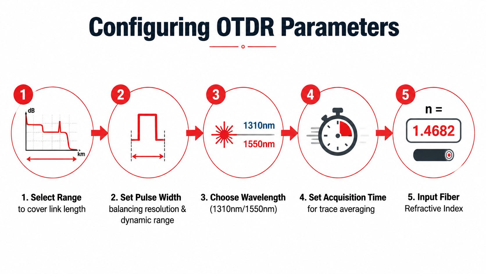
An OTDR does not “scan the fiber.” It measures backscatter and reflections under the conditions the technician sets, so the parameter choices matter as much as the instrument itself. If the range is too short, the trace can stop before the end of the link. If it is too long, the acquisition wastes time and can make the display harder to read. If the pulse width is wrong, nearby events can merge, or they can disappear into noise.
Good setup starts with a disciplined balance. The FOA recommends setting the range to at least twice the cable length, then choosing the shortest pulse width that still provides adequate reach. That trade-off is the core of OTDR work. A shorter pulse improves separation between close events, while a longer pulse extends reach but increases the event dead zone. On a crowded patch field, that difference decides whether you see each connector clearly or get one blurred bump that hides the problem.
Core settings and what they do to the trace
Each parameter changes the shape and usefulness of the trace:
- Range. This sets how far the OTDR expects to look. Too short, and the end of the link is missed. Too long, and the test takes longer than it should.
- Pulse width. Wider pulses reach farther down the fiber, but they enlarge the event dead zone. Narrower pulses sharpen event separation, but they can leave the trace noisy.
- Wavelength. FOA's starting points are 850 nm for multimode and 1310 nm for single-mode. That gives the crew a sensible first pass without guessing.
- Acquisition time. The FOA notes that roughly 16 to 64 averages works for many traces. More averaging cleans the trace, but it also extends test time.
- Refractive index. This value tells the OTDR how to turn time into distance. If it is wrong, the distance readout drifts.
A narrow pulse that is pushed too hard can produce a trace that looks clean while hiding real events. A broad pulse can bury the fault the crew was sent to find.
The refractive index setting deserves special attention on long links. Distance accuracy depends on clock accuracy, data point spacing, the zero-kilometer trigger, and uncertainty in the index of refraction. When those assumptions are off, the fiber can read 1 to 2% longer than the cable itself OTDR handbook.pdf). Parameter entry is not clerical work. It determines whether the reported distance matches the plant and whether the acceptance record can stand up in review.
The technician's judgment matters most when the trace looks good enough. That is where jobs get lost. A trace with a little extra averaging may take longer, but a noisy, uncertain event map costs more in review time, dispute time, and return visits.
Launch and Receive Cable Techniques for Complete Link Characterization
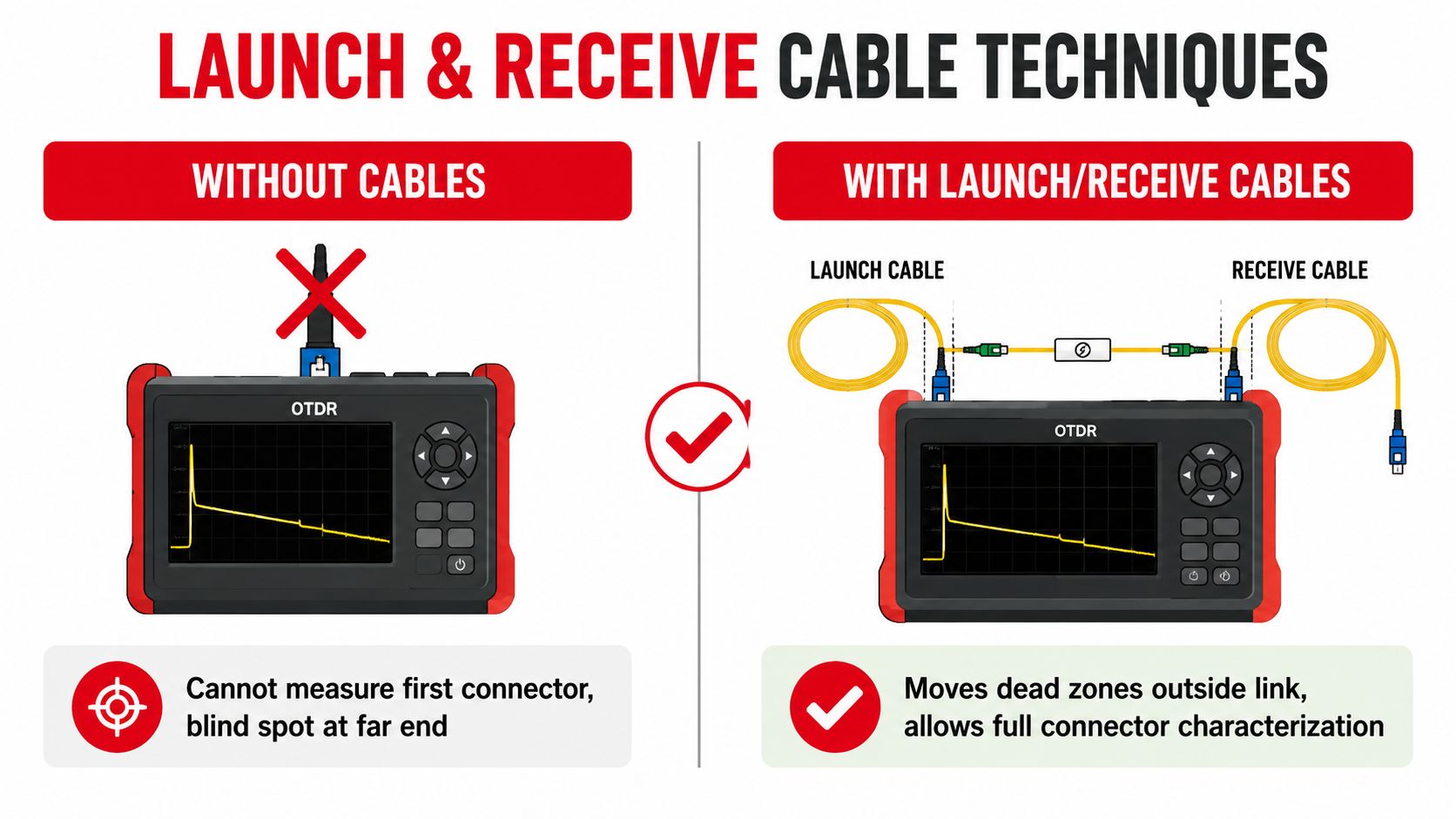
A carrier acceptance job can fall apart on the last connector. The OTDR may show the middle of the link cleanly, but without proper launch and receive cables, the instrument hides the near-end and far-end connections inside its dead zones. Those short blind spots are where crews lose the evidence they need for a complete handoff.
Launch and receive cords move those connectors outside the measured span, so the trace includes the events that matter. That is the point of the setup, not just a nice-to-have accessory for a long reel of fiber. For crews who want a broader primer on the method itself, this OTDR testing overview is a useful reference before field work starts.
The length guidance is practical rather than arbitrary. VIAVI's OTDR guidance says launch and receive cables are generally 300 to 500 m for multimode, 1,000 to 2,000 m for single-mode, and can reach 4,000 m for very long-haul links. If the OTDR supports a multi-pulse function, the launch cable length can be reduced to 20 m VIAVI OTDR guidance. That guidance is tied to the instrument's pulse behavior and dead-zone control.
Why launch and receive cables change the result
Without those cables, the first connector often sits inside the OTDR's near-end blind area. The far end has the same problem. With them in place, both ends can be bracketed outside the measured span, and the trace becomes usable for connector loss, reflection, and event location across the full link.
Bidirectional testing takes that discipline one step further. VIAVI describes it as testing from one end with a launch cable and receive cable, then repeating from the opposite direction so loss values can be compared and averaged VIAVI bidirectional testing. That matters because connector and splice loss can change with launch direction. A single-ended trace can overstate or understate the event loss, and that is how a borderline connector turns into a pointless argument.
A few hard rules keep the method honest:
- Keep the launch cord long enough for the instrument. If it is too short, the first event falls into the dead zone.
- Include the receive cable when the far end matters. Otherwise the last connector stays hidden.
- Test from both directions on acceptance work. Directional bias is a common source of disagreement.
- Do not use an over-wide pulse to force reach. That can hide close events and create a false sense of certainty.
The FOA's setup guidance follows the same logic, markers should bracket the full span so the first and last connections are included, not guessed at. If a crew tries to shortcut that by testing only one direction and one setup, the result may still help with troubleshooting, but it is weak for carrier-grade handoff FOA OTDR quickstart.
Interpreting Traces and Diagnosing Common Fiber Faults
A clean trace only helps when the technician reads it correctly. Reflective events usually point to connectors or mechanical splices. Smooth slope changes usually point to fusion splices. Sharp dips, rough shoulders, or sudden rise-and-fall patterns can point to bends, contamination, or a damaged termination.
The mistake is reading too much into one plot. A bad connector and a dirty connector can look similar at first glance, but the difference usually shows up when the crew inspects the endface and adapter. If the connector cleans up and the trace settles, contamination was the problem. If the ferrule is cracked or the event stays erratic after cleaning, the fault is in the hardware, not the test process.
What the trace can and cannot prove
The best OTDRs offer about 5 cm between data points, while normal resolution is around 8 m. That gap is why marker placement and setup discipline matter so much. Closely spaced events can blend together if the acquisition is sloppy, and no amount of careful reading can recover what the trace never captured.
Distance accuracy also depends on the same four elements named in the OTDR handbook, clock accuracy, data point spacing, zero-kilometer trigger, and index-of-refraction uncertainty. When one of those is off, the distance reading drifts. When several are off, the trace can still look tidy while the reported location is wrong.
If the event map is noisy or the dead zone swallows a suspect section, rework the setup before blaming the fiber.
That saves a lot of unnecessary escalation. Crews waste time chasing a “fault” that was really caused by an over-aggressive pulse width or not enough averaging. In those cases, the right move is to revisit the acquisition parameters, not call for a splice crew.
For a practical refresher on trace reading and basic test flow, this OTDR testing overview is a useful reference when the team needs to keep terminology aligned across troubleshooting, certification, and reporting. Used properly, the trace tells a coherent story. Used casually, it becomes a screenshot with too much confidence attached to it.
Documenting Results and Maintaining Chain of Custody for Acceptance
A good trace without a clean record still gets challenged. Carriers and data center operators want to know which fiber was tested, which direction was used, when the trace was captured, and who handled the file before it reached acceptance review. That's chain of custody, and it's as important as the trace itself.
The report should tie each result to a specific fiber ID, include the bidirectional averaged outcome where required, and present event details in a way that maps back to the build record. If the loss numbers can't be linked to the design loss budget, the report turns into a loose collection of screenshots instead of a deliverable. Good documentation lets the reviewer compare the test to the intended plant, not just to a vague “pass” label.
What belongs in the acceptance packet
A practical packet usually includes:
- Fiber identification. Label the strand, route, and endpoint clearly.
- Trace files. Keep the raw files, not just exported images.
- Event tables. Record connector, splice, and end-of-fiber events in order.
- Bidirectional results. Show the averaged outcome when direction matters.
- Technician sign-off. Make responsibility visible.
- Instrument records. Keep calibration and serial information with the job file.
- Version-controlled as-builts. Tie the test to the current plant record.
A structured documentation process also protects the contractor months later, when a customer asks whether a problem was always there or developed after turnover. That's why documentation best practices matter in the same way clean connectors matter, they make the record trustworthy before anyone starts arguing about fault location.
Field habit that pays off: save the raw trace, the exported report, and the job notes together, every time.
Acceptance work is really a three-part handoff, the fiber, the trace, and the evidence trail. If any one of those is weak, the package is vulnerable. If all three are solid, the test stands up to a review months later, which is exactly what carriers, ISPs, and hyperscale operators expect from serious field work.
If you need OTDR testing support that's built around clean procedure, defensible documentation, and field-ready delivery, Southern Tier Resources can help with testing, troubleshooting, and full project closeout. Visit Southern Tier Resources to connect with a team that treats acceptance work like the audit it is.